ISL6227
Q
is used because when the MOSFET drain-to-source
Choosing MOSFETs
For a notebook battery with a maximum voltage of 24V, at
least a minimum 30V MOSFETs should be used. The design
has to trade off the gate charge with the r
MOSFET:
gd
voltage has fallen to zero, it gets charged. Similarly, the turn-
off time can be estimated based on the gate charge and the
gate drivers sinking current capability.
of the
DS(ON)
The total power loss of the upper MOSFET is the sum of the
switching loss and the conduction loss. The temperature rise
on the MOSFET can be calculated based on the thermal
impedance given on the datasheet of the MOSFET. If the
temperature rise is too much, a different MOSFET package
size, layout copper size, and other options have to be
considered to keep the MOSFET cool. The temperature rise
can be calculated by:
• For the lower MOSFET, before it is turned on, the body
diode has been conducting. The lower MOSFET driver will
not charge the miller capacitor of this MOSFET.
• In the turning off process of the lower MOSFET, the load
current will shift to the body diode first. The high dv/dt of
the phase node voltage will charge the miller capacitor
through the lower MOSFET driver sinking current path.
(EQ.30)
T
= θ P
rise
ja totalpower loss
This results in much less switching loss of the lower
MOSFETs.
The MOSFET gate driver loss can be calculated with the
total gate charge and the driver voltage Vcc. The lower
MOSFET only charges the miller capacitor at turn-off.
The duty cycle is often very small in high battery voltage
applications, and the lower MOSFET will conduct most of
the switching cycle; therefore, the lower the r
lower MOSFET, the less the power loss. The gate charge for
this MOSFET is usually of secondary consideration.
of the
DS(ON)
P
= V
Q F
cc gs sw
(EQ.31)
driver
Based on the above calculation, the system efficiency can
be estimated by the designer.
The upper MOSFET does not have this zero voltage
switching condition, and because it conducts for less time
compared to the lower MOSFET, the switching loss tends to
be dominant. Priority should be given to the MOSFETs with
less gate charge, so that both the gate driver loss, and
switching loss, will be minimized.
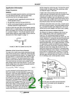
Confining the Negative Phase Node Voltage Swing
with Schottky Diode
At each switching cycle, the body diode of the lower MOSFET
will conduct before the MOSFET is turned on, as the inductor
current is flowing to the output capacitor. This will result in a
negative voltage on the phase node. The higher the load
current, the lower this negative voltage. This voltage will ring
back less negative when the lower MOSFET is turned on.
For the lower MOSFET, its power loss can be assumed to be
the conduction loss only.
2
P
(V ) ≈ (1 – D(V ))I
r
(EQ.26)
lower IN
IN load DS(ON)Lower
A total 400ns period is given to the current sample-and-hold
circuit on the ISEN pin to sense the current going through
the lower MOSFET after the upper MOSFET turns off. An
excessive negative voltage on the lower MOSFET will be
treated as overcurrent. In order to confine this voltage, a
schottky diode can be used in parallel with the lower
MOSFET for high load current applications. PCB layout
parasitics should be minimized in order to reduce the
negative ringing of phase voltage.
For the upper MOSFET, its conduction loss can be written
as:
2
P
(V ) = D(V )I
R
(EQ.27)
uppercond IN
IN load DS(ON)upper
and its switching loss can be written as:
V
I
T
F
V
I T F
IN peak off sw
(EQ.28)
IN vally on sw
P
(V ) = --------------------------------------------- + ----------------------------------------------
uppersw IN
2
2
The second concern for the phase node voltage going into
negative is that the boot strap capacitor between the BOOT
and PHASE pin could get be charged higher than VCC
voltage, exceeding the 6.5V absolute maximum voltage
between BOOT and PHASE when the phase node voltage
became negative. A resistor can be placed between the
cathode of the boot strap diode and BOOT pin to increase
the charging time constant of the boot cap. This resistor will
not affect the turn-on and off of the upper MOSFET.
The peak and valley current of the inductor can be obtained
based on the inductor peak-to-peak current and the load
current. The turn-on and turn-off time can be estimated with
the given gate driver parameters in the Electrical
Specification Table on page 3. For example, if the gate driver
turn-on path of MOSFET has a typical on-resistance of 4Ω,
its maximum turn-on current is 1.2A with 5V Vcc. This
current would decay as the gate voltage increased. With the
assumption of linear current decay, the turn-on time of the
MOSFETs can be written with:
Schottky diode can reduce the reverse recovery of the lower
MOSFET when transition from freewheeling to blocking,
therefore, it is generally good practice to have a schottky
diode closely parallel with the lower MOSFET. B340LA, from
Diodes, Inc.®, can be used as the external schottky diode.
2Q
gd
(EQ.29)
T
= ----------------
on
I
driver
23

 INTERSIL [ Intersil ]