ISL6227
I
is the inductor peak current and not the load current.
Output voltage ripple and the transient voltage deviation are
OC
Since inductor peak current changes with input voltage, it is
better to use an oscilloscope when testing the overcurrent
setting point to monitor the inductor current, and to
determine when the OC occurs. To get consistent test results
on different boards, it is best to keep the MOSFET at a fixed
temperature.
factors that have to be taken into consideration when
selecting an output capacitor. In addition to high frequency
noise related MOSFET turn-on and turn-off, the output
voltage ripple includes the capacitance voltage drop and
ESR voltage drop caused by the AC peak-to-peak current.
These two voltages can be represented by:
I
The MOSFET will not heat-up when applying a very low
frequency and short load pulses with an electronic load to
the output.
pp
∆V = ---------------------
(EQ.22)
(EQ.23)
c
8C F
o
sw
∆V
= I ESR
pp
As an example, assume the following:
esr
• the maximum normal operation load current is 1,
These two components constitute a large portion of the total
output voltage ripple. Several capacitors have to be
paralleled in order to reduce the ESR and the voltage ripple.
If the output of the converter has to support another load
with high pulsating current, more capacitors are needed in
order to reduce the equivalent ESR and suppress the
voltage ripple to a tolerable level.
• the inductor peak current is 1.15-1.3 times higher than the
load current, depending on the inductor value and the
input voltage,
• and the r
DS(ON)
has a 45% increase at higher
temperature.
I
should set at least 1.8 to 2 times higher than the
OC
To support a load transient that is faster than the switching
frequency, more capacitors have to be used to reduce the
voltage excursion during load step change. Another aspect
of the capacitor selection is that the total AC current going
through the capacitors has to be less than the rated RMS
current specified on the capacitors, to prevent the capacitor
from over-heating.
maximum load current to avoid nuisance overcurrent trip.
Selection of the LC Filter
The duty cycle of a buck converter is a function of the input
voltage and output voltage. Once an output voltage is fixed,
it can be written as:
V
o
D(V ) = ---------
(EQ.19)
IN
V
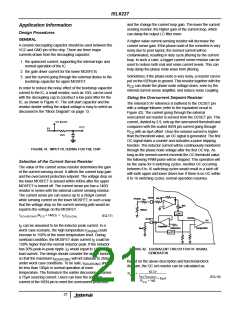
Selection of the Input Capacitor
IN
When the upper MOSFET is on, the current in the output
inductor will be seen by the input capacitor. Even though this
current has a triangular shape top, its RMS value can be
fairly approximated by:
The switching frequency, F , of ISL6227 is 300kHz. The
sw
peak-to-peak ripple current going through the inductor can
be written as:
V (1 – D(V ))
o
IN
(EQ.24)
(EQ.20)
I
= ----------------------------------------
lin
(V ) = D(V )*I
IN load
pp
F
L
rms IN
sw
o
As higher ripple current will result in higher switching loss
and higher output voltage ripple, the peak-to-peak current of
the inductor is generally designed with a 20%-40% peak-to-
peak ripple of the nominal operation current. Based on this
assumption, the inductor value can be selected with the
above equation. In addition to the mechanical dimension, a
shielded ferrite core inductor with a very low DC resistance,
DCR, is preferred for less core loss and copper loss. The DC
copper loss of the inductor can be estimated by:
This RMS current includes both DC and AC components.
Since the DC component is the product of duty cycle and
load current, the AC component can be approximated by:
2
(EQ.25)
li
(V ) = (D(V ) – D(V ) )I
nac IN
IN
IN
load
AC components will be provided from the input capacitor.
The input capacitor has to be able to handle this ripple
current without overheating and with tolerable voltage ripple.
In addition to the capacitance, a ceramic capacitor is
generally used between the drain terminal of the upper
MOSFET and the source terminal of the lower MOSFET, in
order to clamp the parasitic voltage ringing at the phase
node in switching.
2
(EQ.21)
P
= I
DCR
copper
load
The inductor copper loss can be significant in the total
system power loss. Attention has to be given to the DCR
selection. Another factor to consider when choosing the
inductor is its saturation characteristics at elevated
temperature. Saturated inductors could result in nuisance
OC, or OV trip.
22

 INTERSIL [ Intersil ]