ISL6227
The two channels can be programmed to operate in different
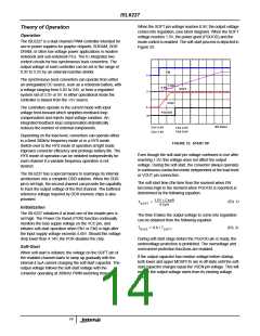
Output Voltage Program
modes depending on the VOUTx connection and the load
current. Once both channels operate in the PWM mode,
however, they will be synchronized to the 300kHz switching
clock. The 180° phase shift reduces the noise couplings
between the two channels and reduces the input current ripple.
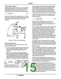
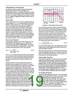
The output voltage of either channel is set by a resistive divider
from the output to ground. The center point of the divider is
connected to the VSEN pin as shown in Figure 34. The
output voltage value is determined by the following equation.
0.9V • (R1 + R2)
V
= ---------------------------------------------
(EQ. 3)
O
The critical discontinuous conduction current value for the
PWM to HYS mode switch-over can be calculated by the
following expression.
R2
where 0.9V is the value of the internal reference. The VSEN
pin voltage is also used by the controller for the power good
function and to detect undervoltage and overvoltage
conditions.
(V – V ) • V
IN
O
O
(EQ. 4)
I
= ----------------------------------------------------
HYS
2 • F
• L • V
SW
O IN
The HYS mode to PWM switch-over current I
HYS1
determined by the activation time of the HYS mode
is
V
IN
Q1
controller. It is affected by the ESR, the inductor value, the
input and output voltage.
UGATE
ISEN
R
CS
L1
V
O
The HYS mode control can improve converter efficiency with
reduced switching frequency. The efficiency is further
improved by the diode emulation scheme in discontinuous
conduction mode. The diode emulation scheme does not
allow the inductor sink current from the output capacitor,
thereby reducing the circulating energy. It is achieved by
sensing the free-wheeling current going through the
synchronous MOSFET through Phase node voltage polarity
change after the upper MOSFET is turned off. Before the
current reverses direction, the lower MOSFET gate pulses
are terminated.
C
C1
Z
Q2
R1
LGATE
VOUT
VSEN
OCSET
ISL6227
R2
R
OC
FIGURE 34. OUTPUT VOLTAGE PROGRAM
The PWM-HYS and HYS-PWM switch-over is provided
automatically by the mode control circuit, which constantly
monitors the inductor current through phase voltage polarity,
and alters the way the gate driver pulse signal is generated.
Operation Mode Control
VOUTx pin programs the two channels of ISL6227 in two
different operational modes:
Mode Transition
For a buck regulator, if the load current is higher than critical
1. If VOUTx is connected to ground, the channel will be put
into a fixed switching frequency of 300kHz CCM, also
known as forced PWM mode regardless of load
conditions.
value I
, the voltage drop on the synchronous MOSFET
HYS1
in the free-wheeling period is always negative, and vice
versa. The mode control circuit monitors the phase node
voltage in the off-period. The polarity of this voltage is used
as the criteria for whether the load current is greater than the
critical value, and thus determines whether the converter will
operate in PWM or HYS mode.
2. If the VOUTx is connected to the output voltage, the
channel will operate in either fixed 300kHz PWM mode or
HYS mode, depending on the load conditions. It operates
in the PWM mode when the load current exceeds the
critical discontinuous conduction value, otherwise it will
operate in a HYS mode, as shown in the following table.
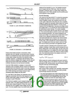
To prevent chatter between operating modes, the circuit
looks for eight sequentially matching polarity signals before it
decides to perform a mode change. The algorithm is true for
both CCM-HYS and HYS-CCM transitions.
INDUCTOR
CURRENT
OPERATION
MODE
VOUT PIN
In the HYS mode, the PWM comparator and the error
amplifier, that provided control in the CCM mode, are put in a
clamped stage and the hysteretic comparator is activated. A
change is also made to the gate logic. The synchronous
MOSFET is controlled in diode emulation fashion, hence the
current in the synchronous MOSFET will be kept in one
direction only. Figures 35 and 36 illustrate the mode change
by counting eight switching cycles.
GND
Any value
Forced PWM
HYS
Connects to output voltage
Connects to output voltage
≤ I
HYS
>I
PWM
HYS1
15

 INTERSIL [ Intersil ]