HSP50110
UPPER LIMIT†
LOWER LIMIT†
AGC THRESHOLD †
LOOP GAIN †
HI/LO OUTPUT SENSE†
LOOP
FILTER
LEVEL
DETECT
LEVEL
DETECT
THRESHOLD FOR
EXTERNAL AGC †
HI/LO
AGC
OEI
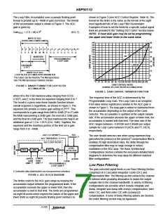
LOW PASS FILTERING
SYNTHESIZER/MIXER
F
O
R
M
11
10
10
12
12
10
IIN0-9
CLK
IOUT0-9
COMPLEX
MULTIPLIER
DATARDY
10
11
A
QOUT0-9
OEQ
QIN0-9
T
ENI
DECIMATING
FILTER
COMPENSATION
COS
SIN
FILTER
INPUT MODE†
10
10
INPUT FORMAT†
PH0-1
32
8
CENTER
FREQUENCY†
DIVIDER
SYNTHESIZER
NCO
CFLD
COF
CLK
PHASE
OFFSET†
SHIFT REG
COFSYNC
RE-SAMPLER
NCO
SSTRB
SPH0-4
5
LOTP
COF EN†
32
SAMPLER CENTER
FREQUENCY†
WORD WIDTH†
SOF EN†
WORD WIDTH†
SOF
SOFSYNC
A0-2
SHIFT REG
RE-SAMPLER
WR
RD
MICROPROCESSOR INTERFACE
C0-7
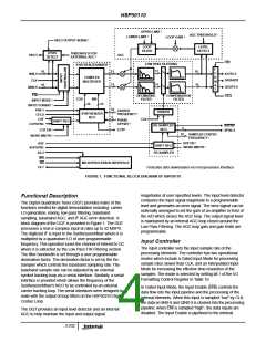
† Indicates data downloaded via microprocessor interface
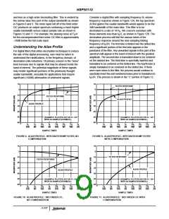
FIGURE 1. FUNCTIONAL BLOCK DIAGRAM OF HSP50110
magnitudes at user specified levels. The input level detector
Functional Description
compares the input signal magnitude to a programmable
level and generates an error signal. The error signal can be
externally averaged to set the gain of an amplifier in front of
the A/D which closes the AGC loop. The output signal level
is maintained by an internal AGC loop closed around the
Low Pass Filtering. The AGC loop gain and gain limits are
programmable.
The Digital Quadrature Tuner (DQT) provides many of the
functions needed for digital demodulation including: carrier
LO generation, mixing, low-pass filtering, baseband
sampling, baseband AGC, and IF AGC error detection. A
block diagram of the DQT is provided in Figure 1. The DQT
processes a real or complex input at rates up to 52 MSPS.
The digitized IF is input to the Synthesizer/Mixer where it is
multiplied by a quadrature LO of user programmable
frequency. This operation tunes the channel of interest to DC
where it is extracted by the Low Pass FIR Filtering section.
The filter bandwidth is set through a user programmable
decimation factor. The decimation factor is set by the Re-
Sampler which controls the baseband sampling rate. The
baseband sample rate can be adjusted by an external
symbol tracking loop via a serial interface. Similarly, a serial
interface is provided which allows the frequency of the
Synthesizer/Mixer’s NCO to be controlled by an external
carrier tracking loop. The serial interfaces were designed to
mate with the output of loop filters on the HSP50210 Digital
Costas Loop.
Input Controller
The input controller sets the input sample rate of the
processing elements. The controller has two operational
modes which include a Gated Input Mode for processing
sample rates slower than CLK, and an Interpolated Input
Mode for increasing the effective time resolution of the
samples. The mode is selected by setting bit 1 of the I/O
Formatting Control Register in Table 10.
In Gated Input Mode, the Input Enable (ENI) controls the
data flow into the input pipeline and the processing of the
internal elements. When this input is sampled “low” by CLK,
the data on IIN0-9 and QIN0-9 is clocked into the processing
pipeline; when ENI is sampled “high”, the data inputs are
disabled. The Input Enable is pipelined to the internal
The DQT provides an input level detector and an internal
AGC to help maintain the input and output signal
3-232

 INTERSIL [ Intersil ]