HIP9011
+5V
V
DD
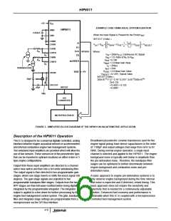
EXAMPLE CASE USING IDEAL SYSTEM EQUATION
HIP9011
VMID
GND
0.022µF
When the Input Signal is Present for the Period t
:
INT
INTOUT (Volts) =
t
CH0NI
CH1NI
SI
SO
1
int
t
c
-- -------
V
× G
×
G
× G
×
×
× G
+ V
DSE RESET
IN
IN
BPR
PR
π
CH1IN
R
SCK
CS
SPI BUS
in
Where:
CH1FB
V
= 200mV , Continuous AC Signal
P-P
IN
R
F
G
= 1.0, Ratio of R to R
CH0IN
IN
F
IN
R
G
= 0.190
= 2.0 Ideal Gain Value
= 200µs
in
PR
INT/HOLD
CH0FB
G
BPF
R
F
t
C
TRANSDUCERS
20pF
t
= 2ms
= 2.0 Ideal Gain Value
= 0.125V, Typical Value
INT
G
+5V
DSE
TEST
OSCIN
V
RESET
INTOUT (Volts) =
-3
-3
-6
4MHz
20pF
200x10 *1* [2 * 0.19 * 0.318 * 2x10 /200x10
*
2]+0.125
=0.4833 + 0.125
=0.608V
OSCOUT
INTOUT
A/D
1MΩ
CONVERTER
MICROPROCESSOR
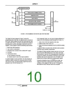
FIGURE 3. SIMPLIFIED BLOCK DIAGRAM OF THE HIP9011 IN AN AUTOMOTIVE APPLICATION
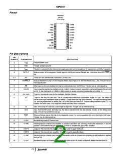
Description of the HIP9011 Operation
This IC is designed to be a universal digitally controlled, analog
interface between engine acoustical sensors or accelerometers
and internal combustion engine fuel management systems.
Two wideband input amplifiers are provided which will allow the
use of two sensors. These sensors be of the piezoelectric type,
that can be mounted in optimum locations on either in-line or V
type engine configurations.
Broadband piezoelectric ceramic transducers used for the
engine signal pickup have device capacitances in the order
of 1100pF and output voltages that range from 5mV to 8V
RMS. During normal engine operation, a single input
channel is selected and applied to the HIP9011. The engine
background noise is typically well below in amplitude than
the pre-detonation noise. Therefore, the bandpass filter
stages can be optimized to further discriminate between
engine background and combustion noise and pre-
detonation noise.
Output from these input amplifiers are directed to a channel
select mux switch and then into a 3rd order antialiasing filter.
The output signal is then directed to two programmable gain
stages, where one stage inverts or shifts the knock signal 180
degrees. The gain stage signals are outputted to two
programmable bandpass filter stages. Outputs from the two
BPF stages are then full wave rectified before being digitally
integrated by the programmable integrator. The integrator
output is applied to a line driver for further processing by the
engine fuel management control system. The gain, bandpass
filter and integrator stage settings are programmable from a
microprocessor via the SPI Bus Interface
A basic approach to engine pre-detonation systems is to
only observe engine background during the time interval
that noise is expected and if detected, retard timing. This
basic approach does not require the sensitivity and
selectivity that is needed for a continuously adjustable
solution. Enhanced fuel economy and performance is
obtainable when this IC is coupled with a microprocessor
controlled fuel management system.
4-6

 INTERSIL [ Intersil ]