BBT3821
under these circumstances, greatly exceeding the elasticity
FIFO’s range, unless the clocks were synchronized. The
CJPAT and CRPAT patterns are those defined by IEEE
802.3ae-2002 Annex 48.
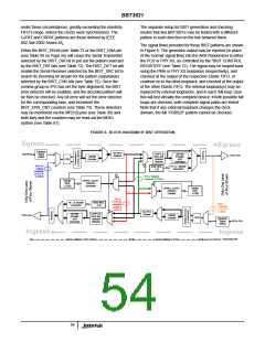
The separate setup for BIST generation and checking
means that two BBT3821s may be tested with a different
pattern in each direction on the link between them.
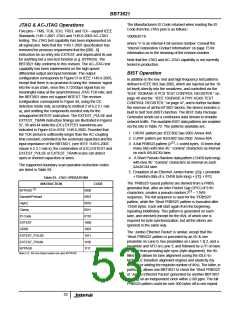
The signal flows provided for these BIST patterns are shown
in Figure 6. The generator output may be injected (in place
of the ‘normal’ signal flow) into the AKR Randomizer in either
the PCS or PHY XS, as controlled by the "BIST CONTROL
REGISTER" (see Table 72). The signal may be looped back
using the PMA or PHY XS loopbacks (respectively), and
checked at the output of the respective Elastic FIFO, or
continue on to the other loopback, and checked at the output
of the other Elastic FIFO. The internal loopback(s) may be
replaced by external loopbacks, and in each ‘full loop’ case
this will test virtually the complete device; if both possible full
loops are checked, both complete signal paths are tested.
Note that if any external loopback changes the clock
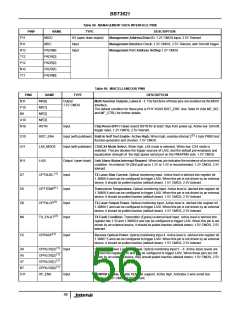
Either the BIST_EN bit (see Table 72 or the BIST_ENA pin
(see Table 99 on Page 56) will cause the Serial Transmitter
selected by the BIST_DIR bit to put out the pattern selected
by the BIST_PAT bits (see Table 72). The BIST_DET bit will
enable the Serial Receiver selected by the BIST_SRC bit to
search its incoming bit stream for the pattern (separately)
selected by the BIST_CHK bits (see Table 72). Once the
comma group or IPG has set the byte alignment, the BIST
error detector will be enabled, and the decoded pattern will
be then be checked. Any bit error will set the error detector
for the corresponding lane, and increment the
BIST_ERR_CNT counters (see Table 73). These detectors
may be monitored via the MF[3:0] pins (see Table 99) and
both they and the counters may be read via the MDIO
system (see Table 81).
domain, the full ‘PRBS23’ pattern cannot be checked.
FIGURE 6. BLOCK DIAGRAM OF BIST OPERATION
Egress
Egress
Equalizer
RX FIFO
Deskew
TXFIFO &
Error and
Orderset
Detector
8B/10B
Encoder,
AKR
RXPnP/N
Signal
Detect
TCXn P/N
10B/8B
CDR
Decoder
Generator
PHY XS
(Serial)
HF, LF, MixedF
Generator
IEEE REG
3.25
Loopback
(4.0.14 &
4.C004)
PCS // Network
Loopback (3.C004)
Vendor
REG
CRPAT, CJPAT,
PRBS23
3.C003
Generater
CRPAT, CJPAT,
Vendor
REG
PRBS23
Checker
3.C003
PCS //
= PHY XS
Loopback
4.C004 &
~3.0.14)
HF, LF, MixedF
IEEE REG
4.25
PMA
Generator
Loopback
(1.0.14 &
1.C004)
RX FIFO
Deskew
8B/10B
Encoder,
AKR
TXFIFO &
Error and
Orderset
Detector
10B/8B
TXPn P/N
CDR
Decoder
Equalizer
Signal
RCXn P/N
Generator
Detect
Ingress
Ingress
MA/PMD
ess 1 P
Device Address 4 PHY XGXS
Device Address 3 PCS
Dev
ice Addr
54

 INTERSIL [ Intersil ]