BBT3821
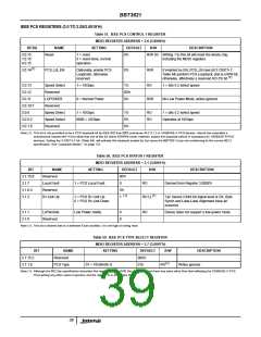
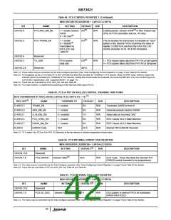
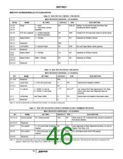
Table 64. PCS CONTROL REGISTER 3 (Continued)
MDIO REGISTER ADDRESS = 3.49153 (3.C001’h)
BIT
3.49153.6
NAME
SETTING
DEFAULT
(1)
R/W
R/W
DESCRIPTION
(4)
PCS AKR_SM_EN
1 = enable random 0’b
A/K/R
Enable pseudo- random A/K/R in Inter Packet Gap
(IPG) on PCS transmitter side (vs. /K/ only)
(3)
0 = /K/ only
(1)
3.49153.5
PCS TRANS_EN
1 = enable
0 = disable
0’b
R/W
R/W
This bit enables the transceiver to translate an “IDLE”
pattern in the internal FIFOs (matching the value of
register 3.C003’h) to and from the XAUI IDLE /K/
comma character or /A/, /K/ & /R/ characters.
(3)
Overridden by
XAUI_EN, see
Table 65
3.49153.4
3.49153.3
Reserved
TX_SDR
(1)
PCS receive
data rate
0’b
1 = PCS egress takes data from PHY XS at half speed
0 = PCS egress takes data from PHY XS at full speed
3.49153.2:0
Reserved
001’b
Note (1): These values may be overwritten by the Auto-Configure operation (See “Auto-Configuring Control Registers” on page 16 and Table 92 for details).
Note (2): PCS loopback via bit 3.0.14 (Table 57) is NOT permitted by IEEE 802.3ae-2002 for 10GBASE-X PCS devices. Many XENPAK hosts, however, expect this
loopback (which is mandatory for 10GBASE-R PCS devices). Setting this bit will enable this loopback, but cause the BBT3821 to be non-conforming to the
current 802.3 specification. See “Loopback Modes ” on page 13).
Note (3): These bits are overridden by PCS XAUI_EN, see also Table 65.
Note (4): This state machine is implemented according to IEEE 802.3ae-2002 clause 48.2.6.
Table 65. PCS or PHY XS XAUI_EN CONTROL OVERRIDE FUNCTIONS
(1)
BITS OVERRIDDEN BY XAUI_EN Bit, D.49153.11 (D.C001’h.11) = 1’b
(1)
REG. BIT
D.49153.5
D.49153.6
D.49152.1
D.49152.4
D.49152.7
D.49154
NAME
TRANS_EN
OVERRIDE TO
1 = enable
DEFAULT
0’b
R/W
R/W
DESCRIPTION
Translates /A/K/R/ to-from /I/
AKR_SM_EN
A_ALIGN_DIS
PCS_SYNC_EN
DSKW_SM_EN
ERROR Code
1 = enable
0 = enabled
1 = enable
1 = enable
FE’h
0’b
R/W
R/W
R/W
R/W
R/W
Generate pseudo-random /A/K/R/
Aligns data on incoming “||A||”
1’b
0’b
IEEE Clause 48.2.6 State Machine
IEEE Clause 48.2.6 State Machine
Internal FIFO ERROR character
0’b
FE’h
Note (1): “D” is either 3 for PCS or 4 for PHY XS. Behavior of the two devices is entirely independent of each other.
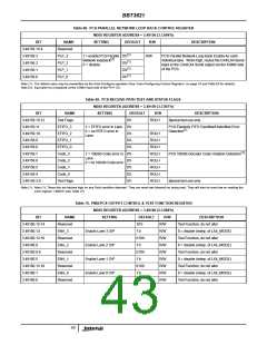
Table 66. PCS INTERNAL ERROR CODE REGISTER
MDIO REGISTER, ADDRESS = 3.49154 (3.C002’h)
(1)
BIT
3.49154.15:8
3.49154.7:0
NAME
Reserved
PCS ERROR
SETTING
DEFAULT
R/W
DESCRIPTION
(2)
Desired Value
FE’h
R/W
Error Code. These bits allow the internal FIFO
ERROR control character to be programmed.
Note (1): The value may be overwritten by the Auto-Configure operation (See “Auto-Configuring Control Registers” on page 16 and Table 92 for details).
Note (2): These bits are overridden to FE’h by XAUI_EN, see Table 64 and Table 65.
Table 67. PCS INTERNAL IDLE CODE REGISTER
MDIO REGISTER ADDRESS = 3.49155 (3.C003’h)
(1)
BIT
3.49155.15:8
3.49155.7:0
NAME
Reserved
PCS XG_IDLE
SETTING
DEFAULT
R/W
DESCRIPTION
Desired Value
07’h
R/W
IDLE pattern in internal FIFOs for translation
to/from XAUI IDLEs
Note (1): The value may be overwritten by the Auto-Configure operation (See “Auto-Configuring Control Registers” on page 16 and Table 92 for details).
42

 INTERSIL [ Intersil ]