BBT3821
VENDOR-SPECIFIC PCS REGISTERS (3.C000’H TO 3.C00E’H)
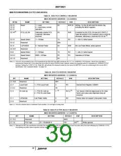
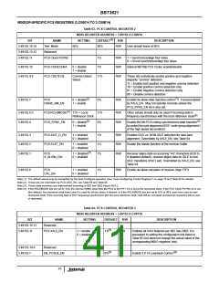
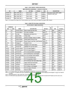
Table 63. PCS CONTROL REGISTER 2
MDIO REGISTER ADDRESS = 3.49152 (3.C000’h)
(1)
BIT
NAME
Test Mode
SETTING
DEFAULT
R/W
R/W
DESCRIPTION
3.49152.15:14
3.49152.13:12
3.49152.11
00’b
00’b
User should leave at 00’b
Reserved
PCS Clock PSYNC
1’b
R/W
R/W
R/W
1 = Synchronize/align four lanes
0 = Do not synchronize/align four lanes
3.49152.10
3.49152.9:8
PCS CODECENA
PCS CDET[1:0]
0 = disable
1 = enable
1’b
Internal 8B/10B PCS Codec enable/disable
Comma Detect
Select
11’b
These bits individually enable positive and negative
disparity “comma” detection.
11 = Enable both positive and negative comma detection
10 = Enable positive comma detection only
01 = Enable negative comma detection only
00 = Disable comma detection
(2)
(3)
3.49152.7
PCS
DSKW_SM_EN
0 = disable
1 = enable
0’b
R/W
Enable De-skew state machine control
. Forced enabled
by XAUI_EN. May not operate correctly unless the
PCS_SYNC_EN bit is also set.
(4)
3.49152.6:5
3.49152.4
PCS RCLKMODE
PCS_SYNC_EN
11’b = Local
11’b
0’b
R/W
R/W
Other values should only be used if incoming data is
frequency-synchronous with the local reference clock
(4)
(3)
Reference Clock
(2)
0 = disable
Enable 8b/10b PCS coding synchronized state machine
to control the byte alignment (IEEE ‘code-group alignment’)
of the high speed de-serializer
1 = enable
3.49152.3
3.49152.2
3.49152.1
PCS IDLE_D_EN
PCS ELST_EN
1 = enabled
0 = disabled
1’b
1’b
1’b
R/W
R/W
R/W
Enables IDLE vs. NON-IDLE detection for lane-lane
alignment. Overridden by XAUI_EN, see Table 64
1 = enabled
0 = disabled
Enable the elastic function of the receiver buffer
(1)
PCS
A_ALIGN_DIS
1 = disabled
0 = enabled
Receiver aligns data on incoming “/A/” characters (K28.3).
If disabled (default), receiver aligns data on IDLE to non-
IDLE transitions (if bit 3 set). Overridden by XAUI_EN, see
Table 64
3.49152.0
PCS
CAL_EN
1 = enabled
0 = disabled
1’b
R/W
Enable de-skew calculator of receiver Align FIFO
Note (1): The default values may be overwritten by the Auto-Configure operation (See “Auto-Configuring Control Registers” on page 16 and Table 92 for details).
Note (2): These bits are overridden by PCS XAUI_EN, see Table 64 and Table 65.
Note (3): These state machines are implemented according to 802.3ae-2002 clause 48.6.2.
Note (4): If the RCLKMODE bits are set to 10’b, the internal XGMII clock from the PCS to the PHY XS is set to the recovered clock. If the PCS Clock PSYNC bit is set
(the default), the recovered clock from Lane 0 is used for all four lanes, if cleared, or if the RCLKMODE bits are set to 01’b or 00’b, each lane uses its own
recovered clock. If the incoming data is NOT frequency-synchronous with the local reference clock, data will be corrupted (occasional characters will be lost,
or repeated).
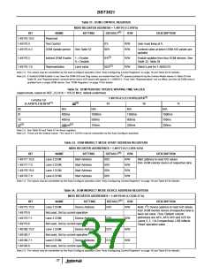
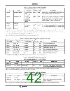
Table 64. PCS CONTROL REGISTER 3
MDIO REGISTER ADDRESS = 3.49153 (3.C001’h)
BIT
NAME
Reserved
SETTING
DEFAULT
R/W
DESCRIPTION
3.49153.15:12
3.49153.11
(1)
PCS XAUI_EN
1 = enable
0 = disable
1’b
R/W
Enables all XAUI features per 802.3ae-2002. It is
equivalent to setting the configuration bits listed in
Table 65 (but does not change the actual value of the
corresponding MDIO registers’ bits).
3.49153.10:8
3.49153.7
Reserved
(1)
(2)
EN_PCSLB_EN
0’b
Enable 3.0.14 Loopback Control
41

 INTERSIL [ Intersil ]