BBT3821
10 Bit Mode
Channel Fault Indications
If a PCS or PHY XS 8B/10B codec is inactive (the respective
XAUI_EN AND CODECENA bits are disabled, see
Any of the above faults (LOS/SIG_DET, Byte Sync, or Lane
Align), will (by default) cause a local fault in the relevant
receiver. If the PCS_SYNC_EN bit at address [3,4]C000’h (or
the XAUI_EN bit at [3:4].C001’h) (see Table 63 to
Table 63/Table 64 & Table 80/Table 81), no 8b/10b coding or
decoding is performed. The incoming bits will be arbitrarily split
into 10 bit bundles in the internal FIFO, optionally based on any
commas received, but otherwise not checked, and must be
retransmitted in the same clock domain, since no elasticity is
possible. Therefore the local reference clock must be frequency
synchronous with the data source. Only the jitter domain will be
reset. System designers must ensure that the data stream is
adequately DC-balanced and contains sufficient transition
density for proper operation, including synchronization.
Table 65 and/or Table 80 to Table 81) is set, the internal FIFOs
will propagate the local fault indication specified in the
IEEE802.3ae-2002 specification (Sections 46.3.4 and 48.2.4.2)
as the Sequence Ordered_Set ||LF|| (see Table 48-4),
/K28.4/D0.0/D0.0/D1.0/, which will be transmitted as the
appropriate XAUI or LX4/CX4 TX output. The BBT3821 lanes
0-3 must be connected to XAUI and LX4/CX4 lanes 0-3 in strict
order. Any Sequence Ordered_Set (including ||LF|| and ||RF||)
received on an input channel will be retransmitted unchanged
on the appropriate output channel.
Error Indications
An equivalent schematic of the various IEEE-defined and
Vendor Specific Fault and Status registers in the BBT3821 is
shown in Figure 4. Those register signals that also contribute to
the LASI system are indicated (see Figure 5).
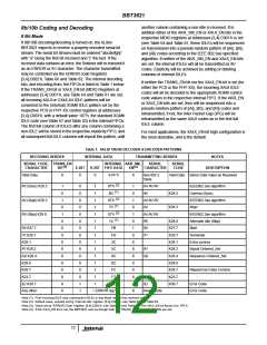
Coding Violation, Disparity & FIFO Errors
The 8b/10b decoder will detect any code violation, and replace
the invalid character by the error character /E/. In the case of a
disparity error, the error may be propagated and only flagged at
the end of a packet (according to the IEEE 802.3 rules). The
BBT3821 will handle this according to those rules. In addition,
the MDIO system includes a flag, in registers [3,4].C007’h on
bits 11:8 (see Table 69 and Table 88). Similarly, an error in the
PCS or PHY XS Elastic (clock compensation) FIFOs will be
flagged in bits 7:4 of the same registers. The FIFO errors may
also be flagged on the MF[3:0] pins via the MDIO MF_SEL and
MF_CTRL register bits (address 4.C001’h, see Table 81).
Loss of Signal
If the reference clock is missing or at an out-of-range frequency,
the PLL in the CMU will fail to lock. This is the only possible
internal cause of a PMA ‘TX Local Fault ‘ indication in bit 1.8.11
(Table 10), and will cause ‘RX Local Fault’ in bit 1.8.10 and
other consequent fault indications (see Table 6, Table 27 and
Table 28).
Loss of the input signal may be caused by poor connections,
insufficient voltage swings, or excessive channel loss. If any of
these conditions occurs, the Loss Of Signal (LOS) and (CX4)
SIG_DET detector outputs on the lane will indicate the fault,
and may be monitored via the MDIO system (see Table 6,
Table 10, Table 27, Table 28, Table 76 and Table 77). See also
the section on “Loss of Signal Detection, Termination &
Equalization“ on page 9 above. In addition, the MDIO MF_SEL
and MF_CTRL register bits (address 4.C001’h, see Table 81)
may be set to provide the LOS/SIG_DET indication on the
MF[3:0] pins.
If a PCS or PHY XS 8B/10B codec is inactive, disparity error
and coding violation errors do not apply, and the FIFOs have no
active error source.
Loopback Modes
In addition to the IEEE 802.3ae-required loopback modes,
the BBT3821 provides a number of additional modes. Each
mode is described in detail below, by reference to the
Detailed Functional Block Diagram in Figure 2, together with
the register bits controlling it.
Byte or Lane Synchronization Failure
PMA Loopback (1.0.0 & 1.C004.[11:8])
The MDIO system can indicate a failure to achieve Byte
Synchronization on any lane, in the PCS register bits 3.24.3:0
(Table 61) or in the PHY XS register bits 4.24.3:0 (Table 78),
which shows the lane-by-lane Byte Sync status. A failure here,
if not caused by any of the above ‘Loss of Signal’ conditions,
would normally reflect a very high bit error rate, or incorrectly
coded data.
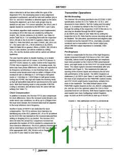
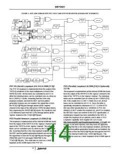
The PMA loopback is implemented from the output of the
TCX[3:0] serializers to the input multiplexers in front of the
RCX[3:0] CDRs. All four lanes are controlled by bit 1.0.0,
while the individual lanes can be controlled (one at a time)
by the 1.C004’h.[11:8] bits. Assuming that this is the only
loopback enabled, and that the BIST and test pattern
generation features are not enabled, the signal flow is from
the RXP[3:0][P/N] pins through almost all the ‘egress’
channel to the input of the (still active) TCX[3:0] output
drivers, then (bypassing the RCX[3:0][P/N] inputs, the
equalizers and LOS detectors) back from the CDRs through
almost all the ‘ingress’ channel to the TXP[3:0][P/N] pins.
Failure of Lane Synchronization is indicated for the PCS by
register bit 3.24.12 (Table 61) or for the PHY XS by register bit
4.24.12 (Table 78), and can be caused by failure to detect /A/
characters on every lane of a channel, by excessive skew
between /A/s on the lanes of a channel, or by inconsistent
skews.
13

 INTERSIL [ Intersil ]