BBT3821
2
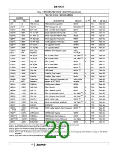
Auto-Configuring Control Registers
I C Space Interface
2
If the XP_ENA pin is asserted, and the I C controller can
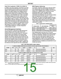
In addition to the standard MDIO registers discussed above,
the BBT3821 implements the register addresses specified in
the XENPAK MSA specification for the NVR, DOM and LASI
2
successfully read the I C NVR space into the MDIO NVR
space, the BBT3821 will examine the Auto-configure Pointer
value at 1.33029 (1.8105’h). If this is neither 00’h or FF’h,
the BBT3821 will use that value (S below) as an offset
2
blocks. The built-in I C controller can be configured to load
these registers with the MSA-specified data on start-up or
2
2
pointer into the A0.00:FF’h I C space already copied into the
reset or on demand from an I C EEPROM (frequently
MDIO NVR space, and the number of bytes given in the
Auto-configure Size register 1.33028 (1.8104) value (N
below) to load N bytes from the NVR data starting from
location S into the various BBT3821 configuration control
registers. The loading sequence and the correspondence
between the NVR block and the control registers is listed in
Table 92. The auto-configure engine will behave benignly if
the S and N values are misconfigured, so that if S + N ≥ 252
(for example), the auto-configure block will stop at an S + N
value of 252, and not use S, N , or the Checksum value to
load a configuration control register. (Hence the exclusion of
FF’h as a value for S is no limitation). Similarly, values of N >
40 will be ignored.
included as part of a DOM circuit) and/or one or four DOM
circuits (see below). Optionally, a portion of the NVR space
may be used to autoload the various BBT3821 control
registers at start-up or reset. These operations are
discussed in more detail below.
NVR Registers & EEPROM
If the XP_ENA pin is asserted enabled (high), at the end of
hardware RESET or power-up the BBT3821 will attempt to
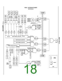
load the NVR area by initiating a NVR-block read through
the 1.32768 (1.8000’h) control register (Table 15). See
Figure 18. The same will occur if the appropriate command
2
value is written into this register. The I C interface will
2
attempt to read the A0.00:FF’h I C space into the
Note that in a XENPAK/XPAK/X2 module, the value of S should
not be between 00’h and 76’h, since this would start the loading
from within the MSA-defined region. (Hence the exclusion of
00’h as a value for S is normally no limitation). If the value of S
lies between 77’h and A6’h, that portion of the auto-configure
data within that band can be overwritten as part of the
1.8007:8106’h MDIO register space. The Command Status
bits in the 1.32768 (1.8000’h) Control register will reflect the
status of this operation. Failure may occur if the expected
ACK is not received from any address after the number of
attempts set in control register 1.32273 (1.8005’h), default
2
63 (Table 20), or if a collision is detected on the I C bus. The
Customer Writable area defined by the MSA specifications; if
this is undesirable, that range of values should also be
timing sequence of this Block Read operation is shown in
Figure 20. The host can check the checksums against the
values at 1.807D, and optionally 1.80AD and 1.8106, and
take appropriate action. As soon as the XENPAK MDIO
space is loaded, the STA MDIO device may interrogate it.
Note that the BBT3821 merely stores the values read from
the EEPROM or other device at A0.00-FF’h, and, with a few
exceptions, does not interpret them in any way. The
exceptions are listed explicitly in Table 22, together with the
other uninterpreted groups, and are:
excluded. On the other hand, this could be used to allow some
customization for specific end-user configuration values. If the
block overlaps the boundary between the ‘Customer Writable’
and ‘Vendor Specific’ areas, the first part would be customer-
writable, and the second part not. The order of the configuration
registers has been arranged to place those most likely to be
useful in such a customer-configuration environment at the
beginning of the block. The ‘Customer Area Checksum’ would
be part of the auto-configure block, and some other byte in the
‘Customer Writeable Area’ would need to be adjusted to make
the Checksum and the desired configuration value coincide.
• The Package OUI at 1.32818:32821 (1.8032:5’h), which
will be mirrored in the IEEE-defined 1.14:15 (1.E:F’h)
space, as required by section 10.8.2 of the XENPAK spec;
the allowable values here are specified by the XENPAK,
XPAK and X2 specifications;
The Command Status bits in the NVR Command register
(Table 15) at 1.32768.3:2 (1.8000’h.3:2) will reflect the success
of both the NVR and (if called for) the auto-configure loading
operations.
• The DOM Capability byte at 1.32890 (1.807A), see the
DOM Registers section, page 16;
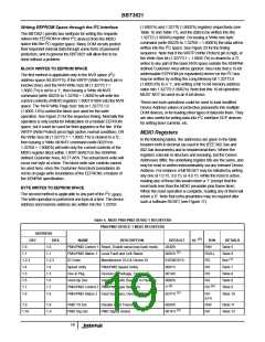
DOM Registers
• The Auto-configure size and pointer bytes at
1.33028:9(1.8104:5); (see Auto-Configuring Control
Registers, page 16).
If the NVR load operation succeeds, the (newly read-in)
XENPAK register at 1.32890 (1.807A’h) is examined, and if the
2
DOM Capability bit is set (bit 6, see Table 23), the I C interface
• If the Auto-configure operation is enabled, the block of
bytes so specified will be written into the BBT3821 control
registers, (see Auto-Configuring Control Registers on
page 16 and Table 92).
2
will attempt to read the DOM values from the I C device
address space specified in the same register (bits 2:0),
normally 001’b pointing to A2’h. See Note (2) to Table 23 for
details. A full block of data will be read from this space (normally
A2.00:FF’h) into the 1.40960:41215 (1.A000: A0FF’h) MDIO
register DOM space. See Figure 18 and Figure 20 for details.
The DOM control register is implemented in the BBT3821 at
Other registers may be interpreted in future versions of the
BBT3821.
16

 INTERSIL [ Intersil ]