BBT3821
be routed to the MF[3:0] pins (see Table 81 and Table 99).
The PMA configuration determines which of these signals
will be reflected in the IEEE PMD Receive signal detect
register at 1.10 (see Table 12), and contribute to the
RX_FAULT bit in the IEEE Status Register 2 at address 1.8
(see Table 10) and the LOCAL_FLT bit in the IEEE
PMA/PMD Status 1 Register, at address 1.1, (see Table 6).
The PHY XGXS LOS will be reflected in the IEEE Status
Registers at addresses 4.8 and 4.1 (see Table 77 and
Table 76). The threshold of the LOS detectors is controlled
via the 'LOS_TH' bits in the MDIO registers at 1.C001'h, see
Table 39, for the PMA/PMD, and for the PHY XS at
4.C001'h, see Table 81.
unless overridden by the respective XAUI_EN bits in the
[3,4].C001’h registers (Table 64 and Table 81). Up to a full
code group may be deleted or modified while aligning the
“comma” code group correctly to the edges of the RefClock.
A comma received at any odd or even byte location, but at
the proper byte boundary, will not cause any byte re-
alignment.
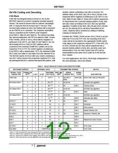
8b/10b Decoding
The internal 10b decoding specified in the IEEE802.3-2002
specification, section 36.2.4 in Tables 36-1 & 36-2, and
discussed in more detail in “8b/10b Coding and Decoding”
page 12, is enabled by default in the PCS and PHY XS
through the setting of the respective CODECENA bits to 1’b,
and may be disabled through the MDIO registers
Clock and Data Recovery
When the 8B/10B coding is used, the line rate receive clock
is extracted from the transition rich 10-bit coded serial data
stream independently on each lane. When 8B/10B coding is
not used, longer run length (up to 512 1’s and 0’s) can be
supported. The data rate of the received serial bit stream
must be within ±100ppm of the nominal bit rate (strictly
within ±200 ppm of the multiplied local reference clock) to
guarantee proper reception. The receive clock locks to the
input within 2µs after a valid input data stream is applied.
The received data is de-serialized and byte aligned.
[3,4].C000’h (Table 63 and Table 80) by setting the
respective bit to 0’b. Note that the transmit encoding will also
be disabled. Although Comma detection will still operate
normally, the PCS_SYNC engine (see above) may not
operate correctly on a proprietary coding scheme, unless
byte sync is performed on K28.5 characters, and no code
violations are to be expected in the proprietary data, and so
should normally be disabled if the 8b/10b coding is turned
off. The ‘fallback’ byte sync operations described above can
still be used, if the encoding scheme meets the “comma”
rules; otherwise they should be disabled also via the CDET
bits, and the user should expect unsynchronized 10-bit data
to be forwarded to the transmitter. No clock compensation is
then possible, and a synchronous reference clock should be
used throughout.
Byte Alignment (Code-Group Alignment)
Unless the CDET bits of the MDIO Registers at address
3.C000’h (for PCS, see Table 63) or 4.C000’h (for PHY XS,
see Table 80) are turned off, the respective Byte Alignment
Units are activated. Each Byte Alignment Unit searches the
coded incoming serial stream for a sequence defined in
IEEE 802.3-2002 Clause 36 as a “comma”. A comma is the
sequence “0011111” or “1100000” depending on disparity,
and is uniquely located in a valid 8B/10B coded data stream,
appearing as the start of some control symbols, including the
/K/ IDLE (K28.5). Comma disparity action can be controlled
via the same CDET bits of the registers [3:4].C000’h (see
Table 63 and Table 80). Any proprietary encoding scheme
used should either incorporate these codes, or arrange byte
alignment differently.
Receive FIFO
The Receive FIFO performs two functions:
1. Lane to Lane Alignment
2. Clock Compensation
Deskew (Lane to Lane) Alignment
Trunking, also known as deskewing, means the alignment of
packet data across multiple lanes. 8 bytes of RXFIFO are
dedicated for this lane to lane alignment in each direction.
During high-speed transmission, different active and passive
elements in the links may impart varying delays in the four
lanes. In trunking mode, multiple lanes share the same clock
(the local reference clock), which is used to transfer data for
output on the serial transmitter.
Upon detection of a comma, the Byte Alignment Unit shifts
the incoming data to align the received data properly in the
10-bit character field. Two possible algorithms may be used
for byte alignment. The default is that specified in the
IEEE802.3ae-2002 clause 48 specification, and is very
robust. This algorithm relies on the 10b/8b decoder, and
should not be used with proprietary encoding/decoding
schemes. The alternative is to byte-align on any comma
pattern. Although quick to align, and normally quite reliable,
this method is susceptible to realignment on certain single bit
errors or on successive K28.7 characters, but could be
preferable for proprietary coding schemes, or during debug.
The algorithm selection is controlled via MDIO register
PCS_SYNC_EN bits, for the PCS at address 3.C000’h
(Table 63), for the PHY XS at address 4.C000’h (Table 80),
Deskewing is accomplished by monitoring the contents of
the FIFOs to detect either an /A/ code-group on every lane
(an ||A|| Ordered_Set), or the boundary between IDLE
sequences and any non-IDLE data (see Table 1); the latter
boundary defines the beginning of the packet. The choice of
which alignment markers to use can be controlled by the
A_ALIGN_DIS bits in MDIO [3,4].C000’h (see for PCS
Table 63 and for PHY XS Table 80), unless overridden by
the respective XAUI_EN bits in the [3,4].C001’h registers
(Table 64 and Table 81) to align on ||A||. When this alignment
10

 INTERSIL [ Intersil ]