82C237
the initial 82C237. This allows the DMA requests of the Autoinitialize - By setting bit 4 in the Mode register, a
additional device to propagate through the priority network channel may be set up as an Autoinitialize channel. During
circuitry of the preceding device. The priority chain is Autoinitialization, the original values of the Current Address
preserved and the new device must wait for its turn to and Current Word Count registers are automatically restored
acknowledge requests. Since the cascade channel of the from the Base Address and Base Word Count registers of the
initial 82C237 is used only for prioritizing the additional channel following EOP. The base registers are loaded simulta-
device, it does not output an address or control signals of its neously with the current registers by the microprocessor and
own. These could conflict with the outputs of the active chan- remain unchanged throughout the DMA service. The mask bit
nel in the added device. The initial 82C237 will respond to is not set when the channel is in Autoinitialize mode. Following
DREQ and generate DACK but all other outputs except HRQ Autoinitialization, the channel is ready to perform another
will be disabled. An external EOP will be ignored by the initial DMA service, without CPU intervention, as soon as a valid
device, but will have the usual effect on the added device.
DREQ is detected, or software request made.
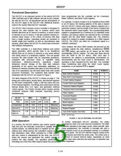
Figure 3 shows two additional devices cascaded with an Memory-to-Memory - To perform block moves of data from
initial device using two of the initial device’s channels. This one memory address space to another with minimum of
forms a two-level DMA system. More 82C237s could be program effort and time, the 82C237 includes a memory-to-
added at the second level by using the remaining channels memory transfer feature. Setting bit 0 in the Command
of the first level. Additional devices can also be added by register selects channels 0 and 1 to operate as memory-to-
cascading into the channels of the second level devices, memory transfer channels.
forming a third level.
The transfer is initiated by setting the software or hardware
DREQ for channel 0. The 82C237 requests a DMA service in
the normal manner. After HLDA is true, the device, using
2ND LEVEL
four-state transfers in Block Transfer mode, reads data from
80C86/88
the memory. The channel 0 Current Address register is the
source for the address used and is decremented or
incremented in the normal manner. The data byte read from
the memory is stored in the 82C237 internal Temporary reg-
ister. Another four-state transfer moves the data to memory
using the address in channel one’s Current Address register
and incrementing or decrementing it in the normal manner.
The channel 1 Current Word Count is decremented.
MICRO-
PROCESSOR
82C237
1ST LEVEL
HRQ
HLDA
HRQ
HLDA
DREQ
DACK
82C237
HRQ
HLDA
DREQ
DACK
82C237
INITIAL DEVICE
When the word count of channel 1 decrements to FFFFH, a
TC is generated causing an EOP output, terminating the
service, and setting the channel 1 TC bit in the Status register.
The channel 1 mask bit will also be set, unless the channel 1
mode register is programmed for autoinitialization. Channel 0
word count decrementing to FFFFH will not set the channel 0
TC bit in the status register or generate an EOP, or set the
channel 0 mask bit in this mode. It will cause an autoinitializa-
tion of channel 0, if that option has been selected.
ADDITIONAL
DEVICES
FIGURE 3. CASCADED 82C237s
When programming cascaded controllers, start with the first
level device (closest to the microprocessor). After RESET,
the DACK outputs are programmed to be active low and are
held in the high state. If they are used to drive HLDA directly,
the second level device(s) cannot be programmed until
DACK polarity is selected as active high on the initial device.
Also, the initial device’s mask bits function normally on
cascaded channels, so they may be used to inhibit second-
level services.
If full Autoinitialization for a memory-to-memory operation is
desired, the channel 0 and channel 1 word counts must be
set to equal values before the transfer begins. Otherwise, if
channel 0 underflows before channel 1, it will autoinitialize
and set the data source address back to the beginning of the
block. If the channel 1 word count underflows before channel
0, the memory-to-memory DMA service will terminate, and
channel 1 will autoinitialize but channel 0 will not.
Transfer Types
Each of the three active transfer modes can perform three
different types of transfers. These are Read, Write and Verify.
Write transfers move data from an I/O device to the memory
by activating MEMW and IOR. Read transfers move data
from memory to an I/O device by activating MEMR and IOW.
In memory-to-memory mode, Channel
0
may be
programmed to retain the same address for all transfers.
This allows a single byte to be written to a block of memory.
This channel 0 address hold feature is selected by setting bit
1 in the Command register.
Verify transfers are pseudo-transfers. The 82C237 operates
as in Read or Write transfers generating addresses and
responding to EOP, etc., however the memory and I/O
control lines all remain inactive. Verify mode is not permitted
for memory-to-memory operation. READY is ignored during
verify transfers.
The 82C237 will respond to external EOP signals during
memory-to-memory transfers, but will only relinquish the
system busses after the transfer is complete (i.e. after an
S24 state). It should be noted that an external EOP cannot
cause the channel 0 Address and Word Count registers to
4-154

 INTERSIL [ Intersil ]