82C237
The 82C237 can assume seven separate states, each Special software commands can be executed by the 82C237
composed of one full CLK period. State I (SI) is the idle in the Program Condition. These commands are decoded as
state. It is entered when the 82C237 has no valid DMA sets of addresses with CS, IOR, and IOW. The commands
requests pending, at the end of a transfer sequence, or do not make use of the data bus. Instructions include Set
when a RESET or Master Clear has occurred. While in SI, and Clear First/Last Flip-Flop, Master Clear, Clear Mode
the DMA controller is inactive but may be in the Program Register Counter, and Clear Mask Register.
Condition (being programmed by the processor).
Active Cycle
State 0 (S0) is the first state of a DMA service. The 82C237
has requested a hold but the processor has not yet returned
When the 82C237 is in the Idle cycle, and a software request
an acknowledge. The 82C237 may still be programmed until
or an unmasked channel requests a DMA service, the device
it has received HLDA from the CPU. An acknowledge from
will issue HRQ to the microprocessor and enter the Active
the CPU will signal the DMA transfer may begin. S1, S2, S3,
cycle. It is in this cycle that the DMA service will take place,
and S4 are the working state of the DMA service. If more
in one of four modes:
time is needed to complete a transfer than is available with
Single Transfer Mode - In single transfer mode, the device
is programmed to make one transfer only. The word count
will be decremented and the address decremented or
incremented following each transfer. When the word count
“rolls over” from zero to FFFFH, a terminal count bit in the
status register is set, an EOP pulse is generated, and the
channel will autoinitialize if this option has been selected. If
not programmed to autoinitialize, the mask bit will be set,
along with the TC bit and EOP pulse.
normal timing, wait states (SW) can be inserted between S3
and S4 in normal transfers by the use of the READY line on
the 82C237. For compressed transfers, wait states can be
inserted between S2 and S4. See timing Figures 14 and 15.
Note that the data is transferred directly from the I/O device
to memory (or vice versa) with IOR and MEMW (or MEMR
and IOW) being active at the same time. The data is not read
into or driven out of the 82C237 in I/O-to-memory or
memory-to-I/O DMA transfers.
DREQ must be held active until DACK becomes active. If
DREQ is held active throughout the single transfer, HRQ will
go inactive and release the bus to the system. It will again go
active and, upon receipt of a new HLDA, another single
transfer will be performed, unless a higher priority channel
takes over. In 8080A, 8085A, 80C88, or 80C86 systems, this
will ensure one full machine cycle execution between DMA
transfers. Details of timing between the 82C237 and other
bus control protocols will depend upon the characteristics of
the microprocessor involved.
Memory-to-memory transfers require a read-from and a write-
to memory to complete each transfer. The States, which
resemble the normal working states, use two-digit numbers
for identification. Eight states are required for a single transfer.
The first four states (S11, S12, S13, S14) are used for the
read-from-memory half and the last four states (S21, S22,
S23, S24) for the write-to-memory half of the transfer.
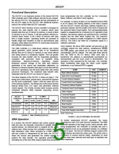
Idle Cycle
When no channel is requesting service, the 82C237 will Block Transfer Mode - In Block Transfer mode, the device is
enter the idle cycle and perform “SI” States. In this cycle, the activated by DREQ or software request and continues
82C237 will sample the DREQ lines on the falling edge of making transfers during the service until a TC, caused by
every CLK cycle to determine if any channel is requesting a word count going to FFFFH, or an external End of Process
DMA service.
(EOP) is encountered. DREQ need only be held active until
DACK becomes active. Again, an Autoinitialization will occur
at the end of the service if the channel has been
programmed for that option.
Note that for standby operation where the clock has been
stopped, DMA requests will be ignored. The device will
respond to CS (chip select), in case of an attempt by the
microprocessor to write or read the internal registers of the Demand Transfer Mode - In Demand Transfer mode the
82C237. When CS is low and HLDA is low, the 82C237 device continues making transfers until a TC or external
enters the Program Condition. The CPU can now establish, EOP is encountered, or until DREQ goes inactive. Thus,
change or inspect the internal definition of the part by read- transfer may continue until the I/O device has exhausted its
ing from or writing to the internal registers.
data capacity. After the I/O device has had a chance to catch
up, the DMA service is reestablished by means of a DREQ.
During the time between services when the microprocessor
is allowed to operate, the intermediate values of address and
word count are stored in the 82C237 Current Address and
Current Word Count registers. Higher priority channels may
intervene in the demand process, once DREQ has gone
inactive. Only an EOP can cause an Autoinitialization at the
end of service. EOP is generated either by TC or by an
external signal.
The 82C237 may be programmed with the clock stopped,
provided that HLDA is low and at least one rising CLK edge
has occurred after HLDA was driven low, so the controller is
in an SI state. Address lines A0-A3 are inputs to the device
and select which registers will be read or written. The IOR
and IOW lines are used to select and time the read or write
operations. Due to the number and size of the internal regis-
ters, an internal flip-flop called the First/Last Flip-Flop is
used to generate an additional bit of address. The bit is used
to determine the upper or lower byte of the 16-bit Address Cascade Mode - This mode is used to cascade more than
and Work Count registers. The flip-flop is reset by Master one 82C237 for simple system expansion. The HRQ and
Clear or RESET. Separate software commands can also set HLDA signals from the additional 82C237 are connected to
or reset this flip-flop.
the DREQ and DACK signals respectively of a channel for
4-153

 INTERSIL [ Intersil ]