Electrical Specifications
impedance. The maximum length of ground wire on the probe should be less than 5 mm. Ensure external
noise from the system is not coupled in the scope probe.
3.
4.
5.
6.
7.
Specified at 90°C T .
Specified at the nominal VCC
Measured at the bulk capacitors on the motherboard.
VCC,BOOT tolerance is shown in Figure 3 and Figure 4.
Based on simulations and averaged over the duration of any change in current. Specified by
design/characterization at nominal VCC. Not 100% tested.
J
.
8.
9.
10.
11.
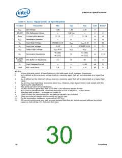
This is a power-up peak current specification, which is applicable when VCCP is high and VCC_CORE is low.
This is a steady-state ICC current specification, which is applicable when both VCCP and VCC_CORE are high.
The VCC max supported by the process is 1.1 V but the parameter can change (burnin voltage is higher).
Unless otherwise noted, all specifications in this table are based on estimates and simulations or empirical
data. These specifications will be updated with characterized data from silicon measurements at a later
date.
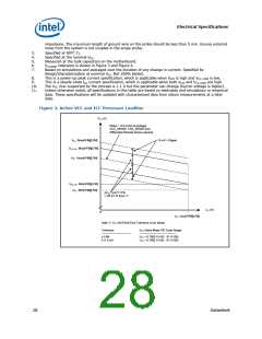
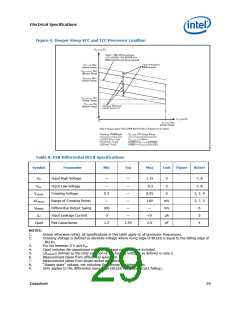
Figure 3. Active VCC and ICC Processor Loadline
VCC (V)
Slope = -5.9 mV/A at package
VCC_SENSE, VSS_SENSE pins.
Differential Remote Sense required.
13 mV = Ripple
VCC Max[HFM][LFM]
VCC, DC Max[HFM][LFM]
VCC Nom[HFM][LFM]
VCC, DC Min[HFM][LFM]
VCC Min[HFM][LFM]
±VCC nom*1.5 %
= VR ST Pt Error 1/
ICC (A)
0
ICC max[HFM][LFM]
Note 1/ VCC Set Point Error Tolerance is per below:
Tolerance
--------------------------------
±1.5%
V
CC Active Mode VID Code Range
----------------------------------------
CC > 0.7500 V (VID 0111100)
VCC 0.7500 V (VID 0111100)
V
±11.5 mV
28
Datasheet

 INTEL [ INTEL ]