Electrical Specifications
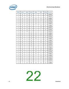
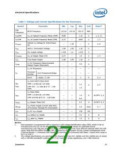
Table 6. Processor Absolute Maximum Ratings
Symbol
TSTORAGE
Parameter
Min
Max
Unit
Notes1,5
Processor Storage Temperature
-40
85
°C
2
Any Processor Supply Voltage with
Respect to VSS
VCC, VCCP
-0.3
-0.1
-0.1
1.10
1.10
1.10
V
V
V
1
AGTL+ Buffer DC Input Voltage
with Respect to VSS
VinAGTL+
1, 2
1, 2
CMOS Buffer DC Input Voltage with
Respect to VSS
VinAsynch_CMOS
NOTES:
1.
2.
This rating applies to the processor and does not include any tray or packaging.
Contact Intel for storage requirements in excess of one year.
3.10
Processor DC Specifications
The processor DC specifications in this section are defined at the processor core
(pads) unless noted otherwise. See Chapter 4 for the pin signal definitions and signal
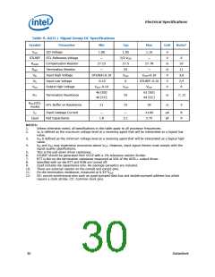
pin assignments. Most of the signals on the FSB are in the AGTL+ signal group. The
DC specifications for these signals are listed in Table 9. DC specifications for the CMOS
group are listed in Table 10.
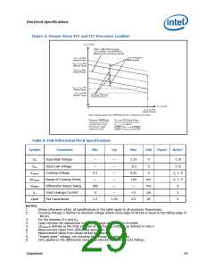
Table 9 through Table 11 list the DC specifications for the processor and are valid only
while meeting specifications for junction temperature, clock frequency, and input
voltages. The Highest Frequency Mode (HFM) and Lowest Frequency Mode (LFM) refer
to the highest and lowest core operating frequencies supported on the processor.
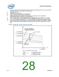
Active mode load line specifications apply in all states except in the Deep Sleep and
Deeper Sleep states. VCC,BOOT is the default voltage driven by the voltage regulator at
power up in order to set the VID values. Unless specified otherwise, all specifications
for the processor are at TJ = 90°C.
Note: Care should be taken to read all notes associated with each parameter.
26
Datasheet

 INTEL [ INTEL ]