Register Description
3.8.3.5
Offset 03h: BCFG—Boot Configuration Register
Offset:
Default Value: 00000000h
03h
Attribute: RW, RO
Size: 32 bits
The Boot Configuration contains information that is only supposed to be accessed by BIOS and is
not for OS use. It contains bits that must be programmed before the OS takes control of interrupts.
Bits
Type
Reset
Description
31:1
0
RO
0
1
Reserved.
RW
Delivery Type (DT): Software sets this bit to 1 to indicate that the delivery
mechanism is as a system bus message and not the I/OxAPIC serial bus.
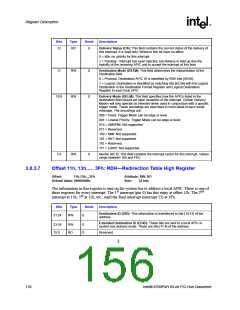
3.8.3.6
Offset 10h, 12h,…, 3Eh: RDL—Redirection Table Low
DWord Register
Offset:
Default Value: 00010000h
10h,12h,..,3Eh
Attribute: RW, RO
Size: 32 bits
The information in this register is sent on the system bus to address a local APIC. There is one of
st
nd
these registers for every interrupt. The 1 interrupt (pin 0) has this entry at offset 10h. The 2
rd
interrupt at 12h, 3 at 14h, etc., until the final interrupt (interrupt 23) at 3Eh.
Bits
Type
Reset
Description
31:18
17
RO
0
0
Reserved.
RW
Disable Flushing Bit (DFLUSH): This bit is maintained for any potential
software compatibility, but the Intel® 6700PXH 64-bit PCI Hub will perform no
flushing action, regardless of the setting of this bit.
16
RW
1
Mask (MSK):
0 = An edge or level on this interrupt pin results in the delivery of the interrupt
to the destination.
1 = Interrupts are not delivered nor held pending. Setting this bit after the
interrupt is accepted by a local APIC has no effect on that interrupt.
15
14
RW
RO
0
0
Trigger Mode (TM): This field indicates the type of signal on the interrupt pin
that triggers an interrupt.
0 = Edge sensitive.
1 = Level sensitive.
Remote IRR (RIRR): This bit is used for level-triggered interrupts; its meaning
is undefined for edge triggered interrupts.
0 = EOI message is received from a local APIC.
1 = For level triggered interrupts, this bit is set when Local APICs accept the
level interrupt sent by the I/OxAPIC. It is reset when an EOI message is
received from a local APIC.
13
RW
0
Interrupt Input Pin Polarity (IP): This bit specifies the polarity of each
interrupt signal connected to the interrupt pins.
0 = Active high.
1 = Active low.
Intel® 6700PXH 64-bit PCI Hub Datasheet
155

 INTEL [ INTEL ]