Functional Description
If this is the first message received (RSTS.PS - D28:F0/F1/F2/F3/F4/F5:Offset 60h:bit
16 is cleared), the root port will set RSTS.PS, and log the PME Requester ID into
RSTS.RID (D28:F0/F1/F2/F3/F4/F5:Offset 60h:bits 15:0). If an interrupt is enabled via
RCTL.PIE (D28:F0/F1/F2/F3/F4/F5:Offset 5Ch:bit 3), an interrupt will be generated.
This interrupt can be either a pin or an MSI if MSI is enabled via MC.MSIE (D28:F0/F1/
F2/F3/F4/F5:Offset 82h:bit 0). See Section 5.2.2.4 for SMI/SCI generation.
If this is a subsequent message received (RSTS.PS is already set), the root port will set
RSTS.PP (D28:F0/F1/F2/F3/F4/F5:Offset 60h:bit 17) and log the PME Requester ID
from the message in a hidden register. No other action will be taken.
When the first PME event is cleared by software clearing RSTS.PS, the root port will set
RSTS.PS, clear RSTS.PP, and move the requester ID from the hidden register into
RSTS.RID.
If RCTL.PIE is set, an interrupt will be generated. If RCTL.PIE is not set, a message will
be sent to the power management controller so that a GPE can be set. If messages
have been logged (RSTS.PS is set), and RCTL.PIE is later written from a 0 to a 1, and
interrupt will be generated. This last condition handles the case where the message
was received prior to the operating system re-enabling interrupts after resuming from
a low power state.
5.2.2.4
SMI/SCI Generation
Interrupts for power management events are not supported on legacy operating
systems. To support power management on non-PCI Express aware operating systems,
PM events can be routed to generate SCI. To generate SCI, MPC.PMCE must be set.
When set, a power management event will cause SMSCS.PMCS (D28:F0/F1/F2/F3/F4/
F5:Offset DCh:bit 31) to be set.
Additionally, BIOS workarounds for power management can be supported by setting
MPC.PMME (D28:F0/F1/F2/F3/F4/F5:Offset D8h:bit 0). When this bit is set, power
management events will set SMSCS.PMMS (D28:F0/F1/F2/F3/F4/F5:Offset DCh:bit 0),
and SMI # will be generated. This bit will be set regardless of whether interrupts or SCI
is enabled. The SMI# may occur concurrently with an interrupt or SCI.
5.2.3
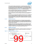
SERR# Generation
SERR# may be generated via two paths – through PCI mechanisms involving bits in the
PCI header, or through PCI Express* mechanisms involving bits in the PCI Express
capability structure.
Figure 5-1. Generation of SERR# to Platform
Secondary Parity Error
PSTS.SSE
PCI
Primary Parity Error
Secondary SERR#
SERR#
PCICMD.SEE
Correctable SERR#
Fatal SERR#
PCI Express
Non-Fatal SERR#
Datasheet
99

 INTEL [ INTEL ]