LPC Interface Bridge Registers (D31:F0)
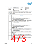
13.8.3.12 SMI_STS—SMI Status Register
I/O Address:
Default Value:
Lockable:
PMBASE + 34h
00000000h
No
Attribute:
Size:
Usage:
RO, R/WC
32-bit
ACPI or Legacy
Power Well:
Core
Note:
If the corresponding _EN bit is set when the _STS bit is set, the ICH10 will cause an
SMI# (except bits 8–10 and 12, which do not need enable bits since they are logic ORs
of other registers that have enable bits). The ICH10 uses the same GPE0_EN register
(I/O address: PMBase+2Ch) to enable/disable both SMI and ACPI SCI general purpose
input events. ACPI OS assumes that it owns the entire GPE0_EN register per ACPI spec.
Problems arise when some of the general-purpose inputs are enabled as SMI by BIOS,
and some of the general purpose inputs are enabled for SCI. In this case ACPI OS turns
off the enabled bit for any GPIx input signals that are not indicated as SCI general-
purpose events at boot, and exit from sleeping states. BIOS should define a dummy
control method which prevents the ACPI OS from clearing the SMI GPE0_EN bits.
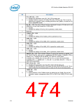
Bit
Description
31:28 Reserved
GPIO_UNLOCK_SMI_STS — R/WC. This bit will be set if the GPIO registers lockdown
logic is requesting an SMI#. Writing a 1 to this bit position clears this bit to 0.
27
26
SPI_STS — RO. This bit will be set if the SPI logic is generating an SMI#. This bit is
read only because the sticky status and enable bits associated with this function are
located in the SPI registers.
25:22 Reserved
MONITOR_STS — RO. This bit will be set if the Trap/SMI logic has caused the SMI.
This will occur when the processor or a bus master accesses an assigned register (or a
sequence of accesses). See Section 10.1.43 through Section 10.1.49 for details on the
specific cause of the SMI.
21
PCI_EXP_SMI_STS — RO. PCI Express* SMI event occurred. This could be due to a
PCI Express PME event or Hot-Plug event.
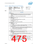
20
19
Reserved
INTEL_USB2_STS — RO. This non-sticky read-only bit is a logical OR of each of the
SMI status bits in the Intel-Specific USB2 SMI Status Register ANDed with the
corresponding enable bits. Additionally, the Port Disable Write Enable SMI is reported in
this bit; the specific status bit for this event is contained in the USB Per-Port Registers
Write Control Register in this I/O space. This bit will not be active if the enable bits are
not set. Writes to this bit will have no effect.
18
17
All integrated USB2 Host Controllers are represented with this bit.
LEGACY_USB2_STS — RO. This non-sticky read-only bit is a logical OR of each of the
SMI status bits in the USB2 Legacy Support Register ANDed with the corresponding
enable bits. This bit will not be active if the enable bits are not set. Writes to this bit will
have no effect.
All integrated USB2 Host Controllers are represented with this bit.
Datasheet
477

 INTEL [ INTEL ]