LPC Interface Bridge Registers (D31:F0)
Bit
Description
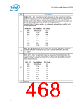
THRM_DTY — WO. This write-once field determines the duty cycle of the throttling
when the FORCE_THTL bit is set. The duty cycle indicates the approximate percentage
of time the STPCLK# signal is asserted while in the throttle mode. The STPCLK#
throttle period is 1024 PCICLKs. Note that the throttling only occurs if the system is in
the C0 state. If in the C2, C3, or C4 state, no throttling occurs.
Once the THRM_DTY field is written, any subsequent writes will have no effect until
PLTRST# goes active.
THRM_DTY Throttle Mode
PCI Clocks
512
000b
001b
010b
011b
100b
101b
110b
111b
50% (Default)
87.5%
75.0%
62.5%
50%
7:5
896
768
640
512
37.5%
25%
384
256
12.5%
128
THTL_EN — R/W. When set and the system is in a C0 state, it enables a processor-
controlled STPCLK# throttling. The duty cycle is selected in the THTL_DTY field.
4
0 = Disable
1 = Enable
THTL_DTY — R/W. This field determines the duty cycle of the throttling when the
THTL_EN bit is set. The duty cycle indicates the approximate percentage of time the
STPCLK# signal is asserted (low) while in the throttle mode. The STPCLK# throttle
period is 1024 PCICLKs.
THTL_DTY
000b
Throttle Mode
50% (Default)
87.5%
PCI Clocks
512
001b
896
3:1
010b
75.0%
768
011b
62.5%
640
100b
50%
512
101b
37.5%
384
110b
25%
256
111b
12.5%
128
0
Reserved
468
Datasheet

 INTEL [ INTEL ]