LPC Interface Bridge Registers (D31:F0)
13.4.2
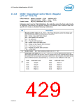
ICW1—Initialization Command Word 1 Register
(LPC I/F—D31:F0)
Offset Address: Master Controller – 20h
Slave Controller – A0h
Attribute:
Size:
WO
8 bit /controller
Default Value:
All bits undefined
A write to Initialization Command Word 1 starts the interrupt controller initialization
sequence, during which the following occurs:
1. The Interrupt Mask register is cleared.
2. IRQ7 input is assigned priority 7.
3. The slave mode address is set to 7.
4. Special mask mode is cleared and Status Read is set to IRR.
Once this write occurs, the controller expects writes to ICW2, ICW3, and ICW4 to
complete the initialization sequence.
Bit
Description
ICW/OCW Select — WO. These bits are MCS-85 specific, and not needed.
7:5
000 = Should be programmed to “000”
ICW/OCW Select — WO.
4
1 = This bit must be a 1 to select ICW1 and enable the ICW2, ICW3, and ICW4
sequence.
Edge/Level Bank Select (LTIM) — WO. Disabled. Replaced by the edge/level
triggered control registers (ELCR, D31:F0:4D0h, D31:F0:4D1h).
3
2
1
ADI — WO.
0 = Ignored for the ICH10. Should be programmed to 0.
Single or Cascade (SNGL) — WO.
0 = Must be programmed to a 0 to indicate two controllers operating in cascade mode.
ICW4 Write Required (IC4) — WO.
0
1 = This bit must be programmed to a 1 to indicate that ICW4 needs to be
programmed.
Datasheet
425

 INTEL [ INTEL ]