LPC Interface Bridge Registers (D31:F0)
13.3.2
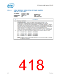
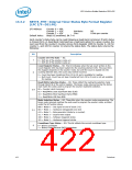
SBYTE_FMT—Interval Timer Status Byte Format Register
(LPC I/F—D31:F0)
I/O Address:
Counter 0 = 40h,
Counter 1 = 41h,
Counter 2 = 42h
Attribute:
Size:
RO
8 bits per counter
Default Value:
Bits[6:0] undefined, Bit 7=0
Each counter's status byte can be read following a Read Back Command. If latch status
is chosen (bit 4=0, Read Back Command) as a read back option for a given counter, the
next read from the counter's Counter Access Ports Register (40h for counter 0, 41h for
counter 1, and 42h for counter 2) returns the status byte. The status byte returns the
following:
Bit
Description
Counter OUT Pin State — RO.
7
0 = OUT pin of the counter is also a 0
1 = OUT pin of the counter is also a 1
Count Register Status — RO. This bit indicates when the last count written to the
Count Register (CR) has been loaded into the counting element (CE). The exact time
this happens depends on the counter mode, but until the count is loaded into the
counting element (CE), the count value will be incorrect.
6
0 = Count has been transferred from CR to CE and is available for reading.
1 = Null Count. Count has not been transferred from CR to CE and is not yet available
for reading.
Read/Write Selection Status — RO. These reflect the read/write selection made
through bits[5:4] of the control register. The binary codes returned during the status
read match the codes used to program the counter read/write selection.
00 = Counter Latch Command
5:4
01 = Read/Write Least Significant Byte (LSB)
10 = Read/Write Most Significant Byte (MSB)
11 = Read/Write LSB then MSB
Mode Selection Status — RO. These bits return the counter mode programming. The
binary code returned matches the code used to program the counter mode, as listed
under the bit function above.
000 = Mode 0 — Out signal on end of count (=0)
001 = Mode 1 — Hardware retriggerable one-shot
x10 = Mode 2 — Rate generator (divide by n counter)
x11 = Mode 3 — Square wave output
3:1
100 = Mode 4 — Software triggered strobe
101 = Mode 5 — Hardware triggered strobe
Countdown Type Status — RO. This bit reflects the current countdown type.
0
0 = Binary countdown
1 = Binary Coded Decimal (BCD) countdown.
422
Datasheet

 INTEL [ INTEL ]