LPC Interface Bridge Registers (D31:F0)
13.4.8
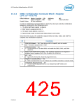
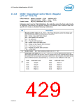
OCW2—Operational Control Word 2 Register
(LPC I/F—D31:F0)
Offset Address: Master Controller – 020h
Slave Controller – 0A0h
Attribute:WO
Size: 8 bits
Default Value:
Bit[4:0]=undefined, Bit[7:5]=001
Following a part reset or ICW initialization, the controller enters the fully nested mode
of operation. Non-specific EOI without rotation is the default. Both rotation mode and
specific EOI mode are disabled following initialization.
Bit
Description
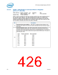
Rotate and EOI Codes (R, SL, EOI) — WO. These three bits control the Rotate and
End of Interrupt modes and combinations of the two.
000 = Rotate in Auto EOI Mode (Clear)
001 = Non-specific EOI command
010 = No Operation
011 = *Specific EOI Command
100 = Rotate in Auto EOI Mode (Set)
101 = Rotate on Non-Specific EOI Command
110 = *Set Priority Command
111 = *Rotate on Specific EOI Command
*L0 – L2 Are Used
7:5
4:3
OCW2 Select — WO. When selecting OCW2, bits 4:3 = “00”
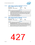
Interrupt Level Select (L2, L1, L0) — WO. L2, L1, and L0 determine the interrupt
level acted upon when the SL bit is active. A simple binary code, outlined below, selects
the channel for the command to act upon. When the SL bit is inactive, these bits do not
have a defined function; programming L2, L1 and L0 to 0 is sufficient in this case.
Code
000b
001b
010b
011b
Interrupt Level
IRQ0/8
Code
000b
001b
010b
011b
Interrupt Level
IRQ4/12
2:0
IRQ1/9
IRQ5/13
IRQ2/10
IRQ6/14
IRQ3/11
IRQ7/15
Datasheet
429

 INTEL [ INTEL ]