LPC Interface Bridge Registers (D31:F0)
13.4.6
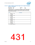
ICW4—Initialization Command Word 4 Register
(LPC I/F—D31:F0)
Offset Address: Master Controller – 021h
Slave Controller – 0A1h
Attribute:WO
Size: 8 bits
Default Value:
01h
Bit
Description
7:5
0 = These bits must be programmed to 0.
Special Fully Nested Mode (SFNM) — WO.
4
0 = Should normally be disabled by writing a 0 to this bit.
1 = Special fully nested mode is programmed.
Buffered Mode (BUF) — WO.
3
2
0 = Must be programmed to 0 for the ICH10. This is non-buffered mode.
Master/Slave in Buffered Mode — WO. Not used.
0 = Should always be programmed to 0.
Automatic End of Interrupt (AEOI) — WO.
1
0
0 = This bit should normally be programmed to 0. This is the normal end of interrupt.
1 = Automatic End of Interrupt (AEOI) mode is programmed.
Microprocessor Mode — WO.
1 = Must be programmed to 1 to indicate that the controller is operating in an Intel
Architecture-based system.
13.4.7
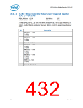
OCW1—Operational Control Word 1 (Interrupt Mask)
Register (LPC I/F—D31:F0)
Offset Address: Master Controller – 021h
Slave Controller – 0A1h
Attribute:R/W
Size: 8 bits
Default Value:
00h
Bit
Description
Interrupt Request Mask — R/W. When a 1 is written to any bit in this register, the
corresponding IRQ line is masked. When a 0 is written to any bit in this register, the
corresponding IRQ mask bit is cleared, and interrupt requests will again be accepted by
the controller. Masking IRQ2 on the master controller will also mask the interrupt
requests from the slave controller.
7:0
428
Datasheet

 INTEL [ INTEL ]