LPC Interface Bridge Registers (D31:F0)
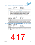
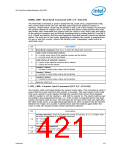
RDBK_CMD—Read Back Command (LPC I/F—D31:F0)
The Read Back Command is used to determine the count value, programmed mode,
and current states of the OUT pin and Null count flag of the selected counter or
counters. Status and/or count may be latched in any or all of the counters by selecting
the counter during the register write. The count and status remain latched until read,
and further latch commands are ignored until the count is read. Both count and status
of the selected counters may be latched simultaneously by setting both bit 5 and bit 4
to 0. If both are latched, the first read operation from that counter returns the latched
status. The next one or two reads, depending on whether the counter is programmed
for one or two byte counts, returns the latched count. Subsequent reads return an
unlatched count.
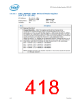
Bit
Description
7:6
Read Back Command. Must be 11 to select the Read Back Command
Latch Count of Selected Counters.
5
4
0 = Current count value of the selected counters will be latched
1 = Current count will not be latched
Latch Status of Selected Counters.
0 = Status of the selected counters will be latched
1 = Status will not be latched
Counter 2 Select.
1 = Counter 2 count and/or status will be latched
3
2
Counter 1 Select.
1 = Counter 1 count and/or status will be latched
Counter 0 Select.
1 = Counter 0 count and/or status will be latched.
1
0
Reserved. Must be 0.
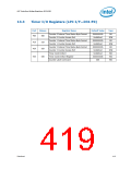
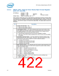
LTCH_CMD—Counter Latch Command (LPC I/F—D31:F0)
The Counter Latch Command latches the current count value. This command is used to
insure that the count read from the counter is accurate. The count value is then read
from each counter's count register through the Counter Ports Access Ports Register
(40h for counter 0, 41h for counter 1, and 42h for counter 2). The count must be read
according to the programmed format, i.e., if the counter is programmed for two byte
counts, two bytes must be read. The two bytes do not have to be read one right after
the other (read, write, or programming operations for other counters may be inserted
between the reads). If a counter is latched once and then latched again before the
count is read, the second Counter Latch Command is ignored.
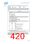
Bit
Description
Counter Selection. These bits select the counter for latching. If “11” is written, then
the write is interpreted as a read back command.
00 = Counter 0
01 = Counter 1
10 = Counter 2
7:6
Counter Latch Command.
5:4
3:0
00 = Selects the Counter Latch Command.
Reserved. Must be 0.
Datasheet
421

 INTEL [ INTEL ]