LPC Interface Bridge Registers (D31:F0)
13.4.3
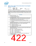
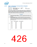
ICW2—Initialization Command Word 2 Register
(LPC I/F—D31:F0)
Offset Address: Master Controller – 21h
Slave Controller – A1h
Attribute:
Size:
WO
8 bit /controller
Default Value:
All bits undefined
ICW2 is used to initialize the interrupt controller with the five most significant bits of
the interrupt vector address. The value programmed for bits[7:3] is used by the
processor to define the base address in the interrupt vector table for the interrupt
routines associated with each IRQ on the controller. Typical ISA ICW2 values are 08h
for the master controller and 70h for the slave controller.
Bit
Description
Interrupt Vector Base Address — WO. Bits [7:3] define the base address in the
interrupt vector table for the interrupt routines associated with each interrupt request
level input.
7:3
Interrupt Request Level — WO. When writing ICW2, these bits should all be 0.
During an interrupt acknowledge cycle, these bits are programmed by the interrupt
controller with the interrupt to be serviced. This is combined with bits [7:3] to form the
interrupt vector driven onto the data bus during the second INTA# cycle. The code is a
three bit binary code:
Code
000b
001b
010b
011b
100b
101b
110b
111b
Master Interrupt
Slave Interrupt
IRQ8
IRQ0
IRQ1
IRQ2
IRQ3
IRQ4
IRQ5
IRQ6
IRQ7
IRQ9
2:0
IRQ10
IRQ11
IRQ12
IRQ13
IRQ14
IRQ15
426
Datasheet

 INTEL [ INTEL ]