LPC Interface Bridge Registers (D31:F0)
13.2.4
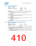
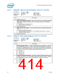
DMACMD—DMA Command Register (LPC I/F—D31:F0)
I/O Address:
Ch. #0–3 = 08h;
Ch. #4–7 = D0h
Undefined
Attribute:WO
Size: 8-bit
Power Well:Core
Default Value:
Lockable:
No
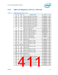
Bit
Description
7:5
Reserved. Must be 0.
DMA Group Arbitration Priority — WO. Each channel group is individually assigned
either fixed or rotating arbitration priority. At part reset, each group is initialized in
fixed priority.
4
0 = Fixed priority to the channel group
1 = Rotating priority to the group.
3
Reserved. Must be 0.
DMA Channel Group Enable — WO. Both channel groups are enabled following part
reset.
2
0 = Enable the DMA channel group.
1 = Disable. Disabling channel group 4–7 also disables channel group 0–3, which is
cascaded through channel 4.
1:0
Reserved. Must be 0.
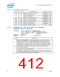
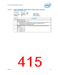
13.2.5
DMASTA—DMA Status Register (LPC I/F—D31:F0)
I/O Address:
Ch. #0–3 = 08h;
Ch. #4–7 = D0h
Undefined
Attribute:RO
Size: 8-bit
Power Well:Core
Default Value:
Lockable:
No
Bit
Description
Channel Request Status — RO. When a valid DMA request is pending for a channel,
the corresponding bit is set to 1. When a DMA request is not pending for a particular
channel, the corresponding bit is set to 0. The source of the DREQ may be hardware or
a software request. Note that channel 4 is the cascade channel, so the request status of
channel 4 is a logical OR of the request status for channels 0 through 3.
7:4
4 = Channel 0
5 = Channel 1 (5)
6 = Channel 2 (6)
7 = Channel 3 (7)
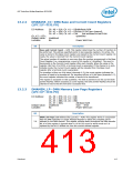
Channel Terminal Count Status — RO. When a channel reaches terminal count (TC),
its status bit is set to 1. If TC has not been reached, the status bit is set to 0. Channel 4
is programmed for cascade, so the TC bit response for channel 4 is irrelevant.
0 = Channel 0
3:0
1 = Channel 1 (5)
2 = Channel 2 (6)
3 = Channel 3 (7)
414
Datasheet

 INTEL [ INTEL ]