LPC Interface Bridge Registers (D31:F0)
13.2.2
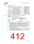
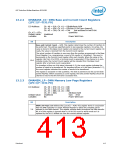
DMABASE_CC—DMA Base and Current Count Registers
(LPC I/F—D31:F0)
I/O Address:
Ch. #0 = 01h; Ch. #1 = 03hAttribute:R/W
Ch. #2 = 05h; Ch. #3 = 07hSize:16-bit (per channel),
Ch. #5 = C6h; Ch. #6 = CAh but accessed in two 8-bit
quantities
Ch. #7 = CEh;
Default Value:
Lockable:
Undefined
No
Power Well:Core
Bit
Description
Base and Current Count — R/W. This register determines the number of transfers to
be performed. The address specified points to two separate registers. On writes, the
value is stored in the Base Count register and copied to the Current Count register. On
reads, the value is returned from the Current Count register.
The actual number of transfers is one more than the number programmed in the Base
Count Register (i.e., programming a count of 4h results in 5 transfers). The count is
decrements in the Current Count register after each transfer. When the value in the
register rolls from 0 to FFFFh, a terminal count is generated. If the channel is in auto-
initialize mode, the Current Count register will be reloaded from the Base Count
register after a terminal count is generated.
15:0
For transfers to/from an 8-bit slave (channels 0–3), the count register indicates the
number of bytes to be transferred. For transfers to/from a 16-bit slave (channels 5–7),
the count register indicates the number of words to be transferred.
The register is accessed in 8 bit quantities. The byte is pointed to by the current byte
pointer flip/flop. Before accessing a count register, the byte pointer flip/flop should be
cleared to ensure that the low byte is accessed first.
13.2.3
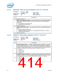
DMAMEM_LP—DMA Memory Low Page Registers
(LPC I/F—D31:F0)
I/O Address:
Ch. #0 = 87h; Ch. #1 = 83h
Ch. #2 = 81h; Ch. #3 = 82h
Ch. #5 = 8Bh; Ch. #6 = 89h
Ch. #7 = 8Ah;
Undefined
No
Attribute:R/W
Default Value:
Lockable:
Size: 8-bit
Power Well:Core
Bit
Description
DMA Low Page (ISA Address bits [23:16]) — R/W. This register works in conjunction
with the DMA controller's Current Address Register to define the complete 24-bit
address for the DMA channel. This register remains static throughout the DMA transfer.
Bit 16 of this register is ignored when in 16 bit I/O count by words mode as it is
replaced by the bit 15 shifted out from the current address register.
7:0
Datasheet
413

 INTEL [ INTEL ]