LPC Interface Bridge Registers (D31:F0)
13.2.8
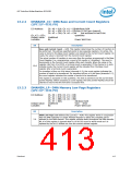
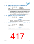
DMA Clear Byte Pointer Register (LPC I/F—D31:F0)
I/O Address:
Ch. #0–3 = 0Ch;
Ch. #4–7 = D8h
xxxx xxxx
Attribute:WO
Size: 8-bit
Power Well:Core
Default Value:
Lockable:
No
Bit
Description
Clear Byte Pointer — WO. No specific pattern. Command enabled with a write to the
I/O port address. Writing to this register initializes the byte pointer flip/flop to a known
state. It clears the internal latch used to address the upper or lower byte of the 16-bit
Address and Word Count Registers. The latch is also cleared by part reset and by the
Master Clear command. This command precedes the first access to a 16-bit DMA
controller register. The first access to a 16-bit register will then access the significant
byte, and the second access automatically accesses the most significant byte.
7:0
13.2.9
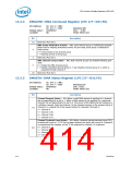
DMA Master Clear Register (LPC I/F—D31:F0)
I/O Address:
Ch. #0–3 = 0Dh;
Ch. #4–7 = DAh
xxxx xxxx
Attribute:WO
Size: 8-bit
Default Value:
Bit
Description
Master Clear — WO. No specific pattern. Enabled with a write to the port. This has the
same effect as the hardware Reset. The Command, Status, Request, and Byte Pointer
flip/flop registers are cleared and the Mask Register is set.
7:0
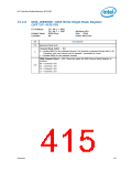
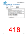
13.2.10 DMA_CLMSK—DMA Clear Mask Register (LPC I/F—D31:F0)
I/O Address:
Ch. #0–3 = 0Eh;
Ch. #4–7 = DCh
xxxx xxxx
Attribute:WO
Size: 8-bit
Power Well:Core
Default Value:
Lockable:
No
Bit
Description
Clear Mask Register — WO. No specific pattern. Command enabled with a write to the
port.
7:0
Datasheet
417

 INTEL [ INTEL ]