Electrical Characteristics
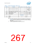
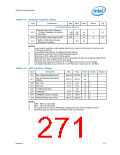
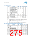
Table 8-11. Universal Serial Bus Timing
Sym
Parameter
Min
Max
Units
Notes
Fig
Full-speed Source (Note 7)
Receiver Data Jitter Tolerance
t113
- To Next Transition- For Paired
Transitions
–152
–200
152
200
ns
ns
3
4
8-8
8-9
t114
t115
EOP Width: Must accept as EOP
670
—
—
ns
ns
Width of SE0 interval during
differential transition
210
NOTES:
1.
Driver output resistance under steady state drive is spec’d at 28 ohms at minimum and
43 ohms at maximum.
2.
3.
4.
5.
6.
7.
8.
Timing difference between the differential data signals.
Measured at crossover point of differential data signals.
Measured at 50% swing point of data signals.
Measured from last crossover point to 50% swing point of data line at leading edge of EOP.
Measured from 10% to 90% of the data signal.
Full-speed Data Rate has minimum of 11.97 Mb/s and maximum of 12.03 Mb/s.
Low-speed Data Rate has a minimum of 1.48 Mb/s and a maximum of 1.52 Mb/s.
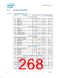
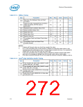
Table 8-12. SATA Interface Timings
Sym
Parameter
Min
Max
Units
Notes
Figure
UI
Gen I Operating Data Period
666.43
670.23
ps
Gen II Operating Data Period
(3Gb/s)
UI-2
333.21
335.11
ps
t120
t121
t122
t123
t124
t125
Rise Time
0.15
0.15
0.41
0.41
UI
UI
ps
ns
ns
ns
1
2
Fall Time
TX differential skew
COMRESET
—
20
310.4
103.5
646.67
329.6
109.9
686.67
3
3
4
COMWAKE transmit spacing
OOB Operating Data period
NOTES:
1.
2.
3.
4.
20% – 80% at transmitter
80% – 20% at transmitter
As measured from 100 mV differential crosspoints of last and first edges of burst.
Operating data period during Out-Of-Band burst transmissions.
Datasheet
271

 INTEL [ INTEL ]