Electrical Characteristics
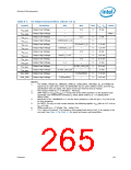
Table 8-9.
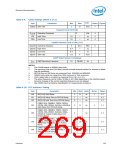
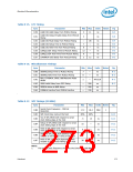
Clock Timings (Sheet 2 of 2)
Unit
Sym
Parameter
Min
Max
Notes Figure
tsatasl
Slew rate
1
8
V/ns
7
Suspend Clock (SUSCLK)
f
Operating Frequency
High Time
32
10
kHz
μs
4
4
4
susclk
t39
—
—
t39a
Low Time
10
μs
Gigabit Internet Clock (GLAN_CLK)
tglanclk Operating Fequency
tglanhi High Time
5
62.5
—
MHz
ns
6
6.4
6.4
1.0
tglanlo Low Time
—
ns
tglansl
Slew rate
4
V/ns
Intel® Quiet System Technology
PWM Operating Frequency 10 28,000
fpwm
Hz
NOTES:
1.
2.
The CLK48 expects a 40/60% duty cycle.
The maximum high time (t18 Max) provide a simple ensured method for devices to detect
bus idle conditions.
3.
4.
5.
6.
BITCLK Rise and Fall times are measured from 10%VDD and 90%VDD.
SUSCLK duty cycle can range from 30% minimum to 70% maximum.
CLK14 edge rates in a system as measured from 0.8 V to 2.0 V.
The active frequency can be 5 MHz, 50 MHz or 62.5 MHz depending on the interface speed.
Dynamic changes of the normal operating frequency are not allowed.
See CK505 Clock Synthesizer Specification for measurement procedure.
7.
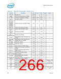
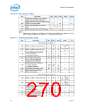
Table 8-10. PCI Interface Timing
Sym
Parameter
Min Max Units
Notes
Figure
t40
t41
t42
AD[31:0] Valid Delay
2
7
0
11
—
—
ns
ns
ns
1
8-2
8-3
8-3
AD[31:0] Setup Time to PCICLK Rising
AD[31:0] Hold Time from PCICLK Rising
C/BE[3:0]#, FRAME#, TRDY#, IRDY#,
STOP#, PAR, PERR#, PLOCK#, DEVSEL#
Valid Delay from PCICLK Rising
t43
t44
2
2
11
28
ns
ns
1
8-2
8-6
C/BE[3:0]#, FRAME#, TRDY#, IRDY#,
STOP#, PAR, PERR#, PLOCK#, IDSEL,
DEVSEL# Output Enable Delay from
PCICLK Rising
C/BE[3:0]#, FRAME#, TRDY#, IRDY#,
STOP#, PERR#, PLOCK#, DEVSEL#,
GNT[A:B]# Float Delay from PCICLK
Rising
t45
t46
2
7
ns
ns
8-4
8-3
C/BE[3:0]#, FRAME#, TRDY#, IRDY#,
STOP#, SERR#, PERR#, DEVSEL#, Setup
Time to PCICLK Rising
Datasheet
269

 INTEL [ INTEL ]