Electrical Characteristics
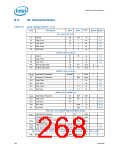
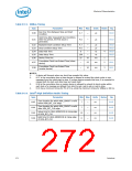
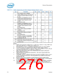
Table 8-13. SMBus Timing
Sym
Parameter
Min
Max
Units
Notes
Fig
Bus Free Time Between Stop and Start
Condition
t130
t131
4.7
—
µs
8-10
Hold Time after (repeated) Start Condition.
After this period, the first clock is
generated.
4.0
—
µs
8-10
t132
t133
t134
t135
t136
Repeated Start Condition Setup Time
Stop Condition Setup Time
Data Hold Time
4.7
4.0
0
—
—
—
—
35
µs
µs
ns
ns
ms
8-10
8-10
8-10
8-10
4
Data Setup Time
250
25
Device Time Out
1
2
Cumulative Clock Low Extend Time (slave
device)
t137
t138
—
—
25
10
ms
ms
8-11
8-11
Cumulative Clock Low Extend Time
(master device)
3
NOTES:
1.
2.
A device will timeout when any clock low exceeds this value.
t137 is the cumulative time a slave device is allowed to extend the clock cycles in one
message from the initial start to stop. If a slave device exceeds this time, it is expected to
release both its clock and data lines and reset itself.
3.
4.
t138 is the cumulative time a master device is allowed to extend its clock cycles within
each byte of a message as defined from start-to-ack, ack-to-ack or ack-to-stop.
t134 has a minimum timing for I2C of 0 ns, while the minimum timing for SMBus is 300 ns.
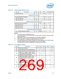
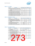
Table 8-14. Intel® High Definition Audio Timing
Sym
Parameter
Min Max
Units
Notes
Fig
Time duration for which HDA_SDOUT is valid
before HDA_BIT_CLK edge.
t143
7
7
—
—
—
—
ns
8-13
Time duration for which HDA_SDOUT is valid
after HDA_BIT_CLK edge.
t144
t145
t146
ns
ns
ns
8-13
8-13
8-13
Setup time for HDA_SDIN[3:0] at rising edge
of HDA_BIT_CLK
15
0
Hold time for HDA_SDIN[3:0] at rising edge
of HDA_BIT_CLK
272
Datasheet

 INTEL [ INTEL ]