Electrical Characteristics
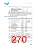
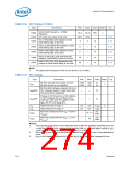
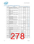
Table 8-18. SPI Timings (33 MHz)
Sym
Parameter
Min
Max
Units Notes
Fig
Serial Clock Frequency - 33 MHz
Operation
t180b
t182b
t183b
30.3
48%
-5
32.19
52%
5
MHz
1
SPI Clock Duty cycle at the host
8-12
8-12
Tco of SPI_MOSI with respect to serial
clock falling edge at the host
ns
ns
ns
ns
ns
Setup of SPI_MISO with respect to serial
clock falling edge at the host
t184b
t185b
8
0
—
—
—
—
8-12
8-12
8-12
8-12
Hold of SPI_MISO with respect to serial
clock falling edge at the host
Setup of SPI_CS[1:0]# assertion with
respect to serial clock rising at the host
t186b
30
30
Hold of SPI_CS[1:0]# deassertion with
respect to serial clock falling at the host
t187b
NOTE:
1.
The typical clock frequency driven by the ICH10 is 31.25 MHz.
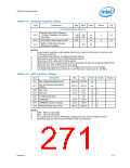
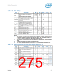
Table 8-19. SST Timings
Sym
Parameter
Min
Max
Units Notes Fig
Bit time (overall time evident on SST)
Bit time driven by an originator
0.495
0.495
500
250
µs
tBIT
1
-
µs
Bit time jitter between adjacent bits in an
SST message header or data bytes after
timing has been negotiated
tBIT,jitter
—
—
—
—
%
Change in bit time across a SST address
or SST message bits as driven by the
originator. This limit only applies across
tBIT,drift
%
tBIT-A bit drift and tBIT-M drift.
tH1
tH0
High level time for logic '1'
0.6
0.2
0.8
0.4
x tBIT
x tBIT
2
High level time for logic '0'
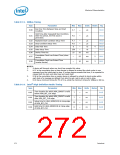
Rise time (measured from VOL = 0.3V to
ns/
node
tSSTR
tSSTF
—
—
25 + 5
33
VIH,min
Fall time (measured from VOH = 1.1V to
VIL,max
)
ns/
node
)
NOTES:
1.
The originator must drive a more restrictive time to allow for quantized sampling errors by
a client yet still attain the minimum time less than 500 µs. tBIT limits apply equally to tBIT-
A and tBIT-M. ICH10 is targeted on 1 Mbps which is 1 µs bit time.
The minimum and maximum bit times are relative to tBIT defined in the Timing Negotiation
pulse.
2.
3.
t
BIT-A is the negotiated address bit time and tBIT-M is the negotiated message bit time.
274
Datasheet

 INTEL [ INTEL ]