Functional Description
5.5.3
Summary of DMA Transfer Sizes
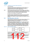
Table 5-10 lists each of the DMA device transfer sizes. The column labeled “Current
Byte/Word Count Register” indicates that the register contents represents either the
number of bytes to transfer or the number of 16-bit words to transfer. The column
labeled “Current Address Increment/Decrement” indicates the number added to or
taken from the Current Address register after each DMA transfer cycle. The DMA
Channel Mode Register determines if the Current Address Register will be incremented
or decremented.
5.5.3.1
Address Shifting When Programmed for 16-Bit I/O Count by Words
Table 5-10. DMA Transfer Size
Current Address
Increment/
Current Byte/Word
Count Register
DMA Device Date Size And Word Count
Decrement
8-Bit I/O, Count By Bytes
Bytes
1
1
16-Bit I/O, Count By Words (Address Shifted)
Words
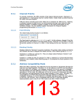
The ICH10 maintains compatibility with the implementation of the DMA in the PC AT
that used the 82C37. The DMA shifts the addresses for transfers to/from a 16-bit
device count-by-words.
Note:
The least significant bit of the Low Page Register is dropped in 16-bit shifted mode.
When programming the Current Address Register (when the DMA channel is in this
mode), the Current Address must be programmed to an even address with the address
value shifted right by one bit.
The address shifting is shown in Table 5-11.
Table 5-11. Address Shifting in 16-Bit I/O DMA Transfers
16-Bit I/O Programmed
Address (Ch 5–7)
(Shifted)
Output
Address
8-Bit I/O Programmed
Address (Ch 0–3)
A0
A0
0
A[16:1]
A[23:17]
A[16:1]
A[23:17]
A[15:0]
A[23:17]
NOTE: The least significant bit of the Page Register is dropped in 16-bit shifted mode.
5.5.4
Autoinitialize
By programming a bit in the DMA Channel Mode Register, a channel may be set up as
an autoinitialize channel. When a channel undergoes autoinitialization, the original
values of the Current Page, Current Address and Current Byte/Word Count Registers
are automatically restored from the Base Page, Address, and Byte/Word Count
Registers of that channel following TC. The Base Registers are loaded simultaneously
with the Current Registers by the microprocessor when the DMA channel is
programmed and remain unchanged throughout the DMA service. The mask bit is not
set when the channel is in autoinitialize. Following autoinitialize, the channel is ready to
perform another DMA service, without processor intervention, as soon as a valid DREQ
is detected.
114
Datasheet

 INTEL [ INTEL ]