Functional Description
®
5.4.1.12
Configuration and Intel ICH10 Implications
LPC I/F Decoders
To allow the I/O cycles and memory mapped cycles to go to the LPC interface, the
ICH10 includes several decoders. During configuration, the ICH10 must be
programmed with the same decode ranges as the peripheral. The decoders are
programmed via the Device 31:Function 0 configuration space.
Note:
The ICH10 cannot accept PCI write cycles from PCI-to-PCI bridges or devices with
similar characteristics (specifically those with a “Retry Read” feature which is enabled)
to an LPC device if there is an outstanding LPC read cycle towards the same PCI device
or bridge. These cycles are not part of normal system operation, but may be
encountered as part of platform validation testing using custom test fixtures.
Bus Master Device Mapping and START Fields
Bus Masters must have a unique START field. In the case of the ICH10 that supports
two LPC bus masters, it drives 0010 for the START field for grants to bus master #0
(requested via LDRQ0#) and 0011 for grants to bus master #1 (requested via
LDRQ1#.). Thus, no registers are needed to configure the START fields for a particular
bus master.
5.5
DMA Operation (D31:F0)
The ICH10 supports LPC DMA using the ICH10’s DMA controller. The DMA controller has
registers that are fixed in the lower 64 KB of I/O space. The DMA controller is
configured using registers in the PCI configuration space. These registers allow
configuration of the channels for use by LPC DMA.
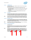
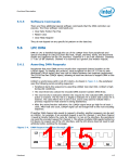
The DMA circuitry incorporates the functionality of two 82C37 DMA controllers with
seven independently programmable channels (Figure 5-3). DMA controller 1 (DMA-1)
corresponds to DMA channels 0–3 and DMA controller 2 (DMA-2) corresponds to
channels 5–7. DMA channel 4 is used to cascade the two controllers and defaults to
cascade mode in the DMA Channel Mode (DCM) Register. Channel 4 is not available for
any other purpose. In addition to accepting requests from DMA slaves, the DMA
controller also responds to requests that software initiates. Software may initiate a
DMA service request by setting any bit in the DMA Channel Request Register to a 1.
Figure 5-3. Intel® ICH10 DMA Controller
Channel 4
Channel 0
Channel 1
Channel 5
Channel 6
Channel 7
DMA-1
DMA-2
Channel 2
Channel 3
Each DMA channel is hardwired to the compatible settings for DMA device size:
channels [3:0] are hardwired to 8-bit, count-by-bytes transfers, and channels [7:5] are
hardwired to 16-bit, count-by-words (address shifted) transfers.
ICH10 provides 24-bit addressing in compliance with the ISA-Compatible specification.
Each channel includes a 16-bit ISA-Compatible Current Register which holds the 16
least-significant bits of the 24-bit address, an ISA-Compatible Page Register which
contains the eight next most significant bits of address.
The DMA controller also features refresh address generation, and auto-initialization
following a DMA termination.
112
Datasheet

 INTEL [ INTEL ]