Functional Description
5.4.1.8
LFRAME# Usage
The ICH10 follows the usage of LFRAME# as defined in the Low Pin Count Interface
Specification, Revision 1.1.
The ICH10 performs an abort for the following cases (possible failure cases):
• ICH10 starts a Memory, I/O, or DMA cycle, but no device drives a valid SYNC after
four consecutive clocks.
• ICH10 starts a Memory, I/O, or DMA cycle, and the peripheral drives an invalid
SYNC pattern.
• A peripheral drives an invalid address when performing bus master cycles.
• A peripheral drives an invalid value.
5.4.1.9
I/O Cycles
For I/O cycles targeting registers specified in the ICH10’s decode ranges, the ICH10
performs I/O cycles as defined in the Low Pin Count Interface Specification, Revision
1.1. These are 8-bit transfers. If the processor attempts a 16-bit or 32-bit transfer, the
ICH10 breaks the cycle up into multiple 8-bit transfers to consecutive I/O addresses.
Note:
If the cycle is not claimed by any peripheral (and subsequently aborted), the ICH10
returns a value of all 1s (FFh) to the processor. This is to maintain compatibility with
ISA I/O cycles where pull-up resistors would keep the bus high if no device responds.
5.4.1.10
Bus Master Cycles
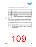
The ICH10 supports Bus Master cycles and requests (using LDRQ#) as defined in the
Low Pin Count Interface Specification, Revision 1.1. The ICH10 has two LDRQ# inputs,
and thus supports two separate bus master devices. It uses the associated START fields
for Bus Master 0 (0010b) or Bus Master 1 (0011b).
Note:
The ICH10 does not support LPC Bus Masters performing I/O cycles. LPC Bus Masters
should only perform memory read or memory write cycles.
5.4.1.11
LPC Power Management
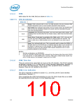
LPCPD# Protocol
Same timings as for SUS_STAT#. Upon driving SUS_STAT# low, LPC peripherals drive
LDRQ# low or tri-state it. ICH10 shuts off the LDRQ# input buffers. After driving
SUS_STAT# active, the ICH10 drives LFRAME# low, and tri-states (or drive low)
LAD[3:0].
Note:
The Low Pin Count Interface Specification, Revision 1.1 defines the LPCPD# protocol
where there is at least 30 µs from LPCPD# assertion to LRST# assertion. This
specification explicitly states that this protocol only applies to entry/exit of low power
states which does not include asynchronous reset events. The ICH10 asserts both
SUS_STAT# (connects to LPCPD#) and PLTRST# (connects to LRST#) at the same time
when the core logic is reset (via CF9h, PWROK, or SYS_RESET#, etc.). This is not
inconsistent with the LPC LPCPD# protocol.
Datasheet
111

 INTEL [ INTEL ]