Functional Description
5.3.6.1.3
FLR Completion
The Initiate FLR bit is reset (cleared) when the FLR reset is completed. This bit can be
used to indicate to the software that the FLR reset is completed.
Note:
From the time Initiate FLR bit is written to 1 software must wait at least 100 ms before
accessing the function.
5.4
LPC Bridge (w/ System and Management
Functions) (D31:F0)
The LPC bridge function of the ICH10 resides in PCI Device 31:Function 0. In addition
to the LPC bridge function, D31:F0 contains other functional units including DMA,
Interrupt controllers, Timers, Power Management, System Management, GPIO, and
RTC. In this chapter, registers and functions associated with other functional units
(power management, GPIO, USB, etc.) are described in their respective sections.
Note:
The LPC bridge cannot be configured as a subtractive decode agent.
5.4.1
LPC Interface
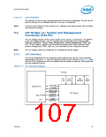
The ICH10 implements an LPC interface as described in the Low Pin Count Interface
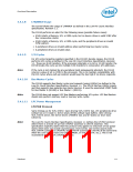
Specification, Revision 1.1. The LPC interface to the ICH10 is shown in Figure 5-2. Note
that the ICH10 implements all of the signals that are shown as optional, but peripherals
are not required to do so.
Figure 5-2. LPC Interface Diagram
PCI Bus
PCI
PCI
PCI
PCI
CLK
RST#
SERIRQ
PME#
LAD [3:0]
Intel® ICH10
LFRAME#
LDRQ[1:0]#
(Optional)
LPC Device
LPCPD#
SUS_STAT#
GPI
(Optional)
LSMI#
(Optional)
Datasheet
107

 INTEL [ INTEL ]