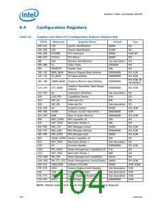
Graphics, Video, and Display (D2:F0)
9.4
Configuration Registers
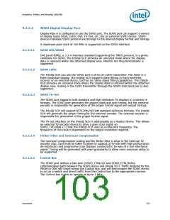
Table 25.
Graphics and Video PCI Configuration Register Address Map
Offset
Mnemonic
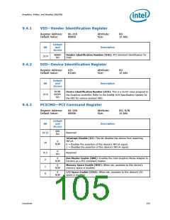
VID
Register Name
Vendor Identification
Default
8086h
Type
00h–01h
02h–03h
04h–05h
06h–07h
08h
RO
RO
DID
Device Identification
PCI Command
8108h
PCICMD
PCISTS
RID
0000h
R/W, RO
RO
PCI Status
0000h
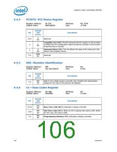
Revision Identification
Class Codes
see description
03U000h
00h
RO
09h–0Bh
0Eh
CC
RO
HEADTYP
MEM_BASE
IO_BASE
Header Type
RO
10h–13h
14h–17h
Memory Mapped Base Address
I/O Base Address
00000000h
00000000h
RO, R/W
RO, R/W
RO, R/W, R/
WLOR/WLO
18h–1Bh
1Ch–1Fh
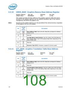
GMEM_BASE Graphics Memory Base Address
00000000h
00000000h
Graphics Translation Table Range
GTT_BASE
Address
RO, R/W
2Ch–2Fh
34h
SS
Subsystem Identifiers
Capabilities Pointer
Interrupt Line
See description
D0h
RO
CAP_PTR
INT_LN
INT_PN
GC
RO
3Ch
00h
RO
3Dh
Interrupt Pin
See description
0030h
RO
52h–53h
58h–5Bh
5Ch–5Fh
90h
Graphics Control
RO, R/W
R/W
SSRW
Software Scratch Read Write
Base of Stolen Memory
MSI Capability ID
00000000h
00000000h
05h
BSM
RO, R/W
RO
MSI_CAPID
NXT_PTR3
MSI_CTL
MSI_ADR
MSI_DATA
91h
Next Item Pointer 3
MSI Message Control
MSI Message Address
MSI Message Data
00h
RO
92h–93h
94h–97h
98h–99h
B0h
0000h
RO, R/W
RO, R/W
RO, R/W
RO
00000000h
0000h
VEND_CAPID Vendor Capability ID
09h
B1h
NXT_PTR2
FD
Next Item Pointer 2
See description
00000000h
01h
RO
C4h
Function Disable
RO, R/W
RO
D0h
PM_CAPID
NXT_PTR1
PM_CAP
Power Management Capabilities ID
Next Item Pointer 1
D1h
B0h
RO
D2h–D3h
D4h–D5h
E0h–E1h
E4h–E7h
F0h
Power Management Capabilities
0022h
RO
PM_CTL_STS Power Management Control/Status 0000h
RO, R/W
R/W, R/WO
R/W
SWSCISMI
ASLE
Software SCI/SMI
0000h
System Display Event Register
Graphics Clock Ratio
Legacy Backlight Brightness
ASL Storage
See description
See description
See description
00000000h
GCR
R/W
F4h–F7h
FCh–FFh
LBB
R/W
ASLS
R/W
NOTE: Address locations that are not shown should be treated as Reserved.
104
Datasheet

 INTEL [ INTEL ]