Graphics, Video, and Display (D2:F0)
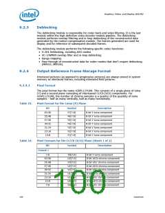
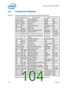
Table 24.
Pixel Formats for the Cr/Cb (V/U) Plane (Sheet 2 of 2)
Bit
Symbol
Description
Format 2 (Cr and Cb are reversed relative to Format 1)
63:56
55:48
47:40
39:32
31:24
23:16
15:8
V3[7:0]
U3[7:0]
V2[7:0]
U2[7:0]
V1[7:0]
U1[7:0]
V0[7:0]
U0[7:0]
8-bit U/Cr chroma component
8-bit V/Cb chroma component
8-bit U/Cr chroma component
8-bit V/Cb chroma component
8-bit U/Cr chroma component
8-bit V/Cb chroma component
8-bit U/Cr chroma component
8-bit V/Cb chroma component
7:0
9.3
Display Overview
The Intel® SCH display output can be divided into three stages:
• Planes
— Request/Receive data from memory
— Format memory data into pixels
— Handle fragmentation, tiling, physical address mapping
• Pipes
— Generate display timing
— Scaling, LUT
• Ports
— Format pixels for output (SDVO, LVDS)
— Interface to physical layer
9.3.1
Planes
The Intel® SCH contains a variety of planes (such as, Display and Cursor). A plane
consists of rectangular shaped image that has characteristics (such as, source, size,
position, method, and format). These planes get attached to source surfaces, which are
rectangular areas in memory with a similar set of characteristics. They are also
associated with a particular destination pipe.
• Display Plane - The primary and secondary display plane works in an indexed
mode, hi-color mode or a true color mode. The true color mode allows for an 8-bit
alpha channel. One of the primary operations of the display plane is the set mode
operation. The set-mode operation occurs when it is desired to enable a display,
change the display timing, or source format. The secondary display plane can be
used as a primary surface on the secondary display or as a sprite planes on either
the primary or secondary display.
• Cursor Plane - The cursor plane is one of the simplest display planes. With a few
exceptions, the cursor plane supports sizes of 64 x 64, 128 x 128 and 256 x 256
fixed Z-order (top). In legacy modes, cursor can cause the display data below it to
be inverted.
• VGA Plane - VGA mode provides compatibility for pre-existing software that set the
display mode using the VGA CRTC registers. VGA Timings are generated based on
the VGA register values (the hi-resolution timing generator registers are not used).
Note:
The Intel® SCH has limited support for a VGA Plane. The VGA plane is suitable for
usages such as BIOS boot screens, pre-OS splash screens, etc. Other usages of the
VGA plane (like DOS-based games, for example) are not supported.
Datasheet
101

 INTEL [ INTEL ]