GMCH Register Description
4.3.2
PCI Express* Enhanced Configuration Mechanism
PCI Express extends the configuration space to 4096 bytes per device/function as
compared to 256 bytes allowed by PCI Specification Revision 2.3. PCI Express
configuration space is divided into a PCI 2.3 compatible region, which consists of the
first 256B of a logical device’s configuration space and a PCI Express extended region
which consists of the remaining configuration space.
The PCI compatible region can be accessed using either the Standard PCI
Configuration Mechanism or using the PCI Express Enhanced Configuration Mechanism
described in this section. The extended configuration registers may only be accessed
using the PCI Express Enhanced Configuration Mechanism. To maintain compatibility
with PCI configuration addressing mechanisms, system software must access the
extended configuration space using 32-bit operations (32-bit aligned) only. These 32-
bit operations include byte enables allowing only appropriate bytes within the DWord
to be accessed. Locked transactions to the PCI Express memory mapped configuration
address space are not supported. All changes made using either access mechanism
are equivalent.
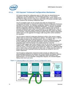
The PCI Express Enhanced Configuration Mechanism utilizes a flat memory-mapped
address space to access device configuration registers. This address space is reported
by the system firmware to the operating system. There is a register, PCI
EXPRESS*XBAR, that defines the base address for the block of addresses below 4GB
for the configuration space associated with busses, devices and functions that are
potentially a part of the PCI Express root complex hierarchy. In the PCI
EXPRESS*XBAR register there exists controls to limit the size of this reserved memory
mapped space. 256MB is the amount of address space required to reserve space for
every bus, device, and function that could possibly exist. Options for 128MB and 64MB
exist in order to free up those addresses for other uses. In these cases the number of
busses and all of their associated devices and functions are limited to 128 or 64
busses respectively.
The PCI Express Configuration Transaction Header includes an additional 4 bits
(ExtendedRegisterAddress[3:0]) between the Function Number and Register Address
fields to provide indexing into the 4 KB of configuration space allocated to each
potential device. For PCI Compatible Configuration Requests, the Extended Register
Address field must be all zeros.
Figure 4-2. Memory Map to PCI Express* Device Configuration Space
0x7FFF
0xFFF
0xFFFFFFF
0xFFFFF
Bus 255
Device 31
Function 7
PCI Express
Extended
Configuration
Space
0xFF
0x3F
PCI Compatible
Configuration
Space
0xFFFF
0x7FFF
0x1FFF
0xFFF
0x1FFFFF
0xFFFFF
Device 1
Device 0
Function 1
Function 0
Bus 1
Bus 0
PCI Compatible
Configuration
Space Header
0
Located by
PCI Express* Base Address
70
Datasheet

 INTEL [ INTEL ]