GMCH Register Description
4.2
Configuration Process and Registers
4.2.1
Platform Configuration Structure
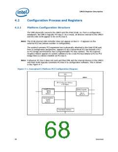
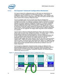
The DMI physically connects the GMCH and the Intel ICH8; so, from a configuration
standpoint, the DMI is logically PCI bus 0. As a result, all devices internal to the GMCH
and the Intel ICH8 appear to be on PCI bus 0.
Note: The ICH8 internal LAN controller does not appear on bus 0 – it appears on the
external PCI bus (whose number is configurable).
The system’s primary PCI expansion bus is physically attached to the Intel ICH8 and,
from a configuration perspective, appears to be a hierarchical PCI bus behind a PCI-
to-PCI bridge and therefore has a programmable PCI Bus number. The PCI Express
Graphics Attach appears to system software to be a real PCI bus behind a PCI-to-PCI
bridge that is a device resident on PCI bus 0.
Note: A physical PCI bus 0 does not exist and that DMI and the internal devices in the GMCH
and Intel ICH8 logically constitute PCI Bus 0 to configuration software. This is shown
in the Figure 4-1.
Figure 4-1. Conceptual G Platform PCI Configuration Diagram
68
Datasheet

 INTEL [ INTEL ]