Direct Memory Interface (DMI) Registers
7 Direct Memory Interface (DMI)
Registers
This Root Complex Register Block (RCRB) controls the GMCH-ICH9 serial interconnect.
The base address of this space is programmed in DMIBAR in D0:F0 configuration
space. Table 7-1 provides an address map of the DMI registers listed by address offset
in ascending order. Section 7.1 provides register bit descriptions.
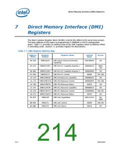
Table 7-1. DMI Register Address Map
Address
Offset
Register
Symbol
Register Name
Default
Value
Access
00–03h
04–07h
DMIVCECH
DMI Virtual Channel Enhanced
Capability
04010002h
00000001h
RO
DMIPVCCAP1
DMI Port VC Capability Register 1
RWO,
RO
08–0Bh
0C–0Dh
10–13h
14–17h
1A–1Bh
1C–1Fh
20–23h
26–27h
84–87h
DMIPVCCAP2
DMIPVCCTL
DMI Port VC Capability Register 2
DMI Port VC Control
00000000h
0000h
RO
RO, RW
RO
DMIVC0RCAP
DMIVC0RCTL0
DMIVC0RSTS
DMIVC1RCAP
DMIVC1RCTL1
DMIVC1RSTS
DMILCAP
DMI VC0 Resource Capability
DMI VC0 Resource Control
DMI VC0 Resource Status
DMI VC1 Resource Capability
DMI VC1 Resource Control
DMI VC1 Resource Status
DMI Link Capabilities
00000001h
800000FFh
0002h
RO, RW
RO
00008001h
01000000h
0002h
RO
RW, RO
RO
00012C41h
RO,
RWO
88–89h
8A–8Bh
DMILCTL
DMILSTS
DMI Link Control
DMI Link Status
0000h
0001h
RW, RO
RO
214
Datasheet

 INTEL [ INTEL ]