PCI Express* Registers (D1:F0)
6.1.40
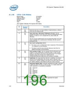
LSTS—Link Status
B/D/F/Type:
Address Offset:
Default Value:
Access:
0/1/0/PCI
B2–B3h
1001h
RO
Size:
16 bits
This register indicates PCI Express link status.
“
Bit
15:14
13
Access &
Default
Description
RO
00b
Reserved and Zero: For future R/WC/S implementations; software
must use 0 for writes to bits.
RO
0b
Data Link Layer Link Active (Optional) (DLLLA): This bit
indicates the status of the Data Link Control and Management State
Machine. It returns a 1b to indicate the DL_Active state, 0b
otherwise.
This bit must be implemented if the corresponding Data Link Layer
Active Capability bit is implemented. Otherwise, this bit must be
hardwired to 0b.
12
11
RO
1b
Slot Clock Configuration (SCC):
0 = The device uses an independent clock irrespective of the presence
of a reference on the connector.
1 = The device uses the same physical reference clock that the
platform provides on the connector.
RO
0b
Link Training (LTRN): This bit indicates that the Physical Layer
LTSSM is in the Configuration or Recovery state, or that 1b was
written to the Retrain Link bit but Link training has not yet begun.
Hardware clears this bit when the LTSSM exits the
Configuration/Recovery state once Link training is complete.
10
RO
0b
Undefined: The value read from this bit is undefined. In previous
versions of this specification, this bit was used to indicate a Link
Training Error. System software must ignore the value read from this
bit. System software is permitted to write any value to this bit.
9:4
RO
00h
Negotiated Width (NW): Indicates negotiated link width. This field
is valid only when the link is in the L0, L0s, or L1 states (after link
width negotiation is successfully completed).
00h = Reserved
01h = X1
02h = Reserved
04h = Reserved
08h = Reserved
10h = X16
All other encodings are reserved.
Negotiated Speed (NS): Indicates negotiated link speed.
1h = 2.5 Gb/s
3:0
RO
1h
All other encodings are reserved.
196
Datasheet

 INTEL [ INTEL ]