INTEL StrataFlash™ MEMORY TECHNOLOGY, 32 AND 64 MBIT
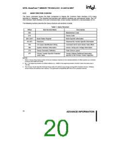
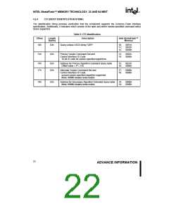
4.2.2 QUERY STRUCTURE OVERVIEW
E
The Query command causes the flash component to display the Common Flash Interface (CFI) Query
structure or “database.” The structure sub-sections and address locations are summarized below. See AP-
646 Common Flash Interface (CFI) and Command Sets (order number 292204) for a full description of CFI.
The following sections describe the Query structure sub-sections in detail.
Table 7. Query Structure
Offset
00h
Sub-Section Name
Description
Manufacturer Code
01h
Device Code
(BA+2)h(2)
04–0Fh
10h
Block Status Register
Block-Specific Information
Reserved
Reserved for Vendor-Specific Information
Command Set ID and Vendor Data Offset
Device Timing and Voltage Information
Flash Device Layout
CFI Query Identification String
System Interface Information
Device Geometry Definition
1Bh
27h
P(3)
Primary Vendor-Specific Extended
Query table
Vendor-Defined Additional Information
Specific to the Primary Vendor Algorithm
NOTES:
1. Refer to Query Data Output section of Device Hardware interface for the detailed definition of offset address as a function
of device word width and mode.
2. BA = The beginning location of a Block Address (i.e., 2000h is the beginning location of block 2 when the block size is
128 KB).
3. The Primary Vendor-Specific Extended Query table (P) address may change among SCS-compliant devices. Software
should retrieve this address from address 15 to guarantee compatibility with future SCS-compliant devices.
20
ADVANCE INFORMATION

 INTEL [ INTEL ]