Ultra-Low Voltage Intel® Celeron® Processor — 650 MHz and 400 MHz
Table 32. PICCLK DC Specifications and AC Signal Quality Specifications
Symbol
Parameter
Min Max Unit
Figure
Notes
V1
V2
VIL20
VIH20
0.4
2.4
0.4
V
V
V
V
V
18
18
18
18
18
1
1.6
-0.5
1.6
1
V3
V
IN Absolute Voltage Range
Undershoot, Overshoot, 2
Absolute Value, 3
Absolute Value, 3
V4
PICCLK Rising Edge Ringback
PICCLK Falling Edge Ringback
V5
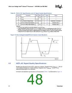
NOTES:
1. The clock must rise/fall monotonically between V
2. These specifications apply only when PICCLK is running. See the DC specifications for when PICCLK is
and V
.
IL20
IH20
stopped. PICCLK may not be above V
3. The rising and falling edge ringback voltage specified is the minimum (rising) or maximum (falling) absolute
or below V
for more than 50% of the clock cycle.
IH20,max
IL20,min
voltage the PICCLK signal may go to after passing the V
(rising) or V
(falling) voltage limits.
IH20
IL20
Figure 19. BCLK (Single Ended)/PICCLK Generic Clock Waveform
V3max
V4
V2
V1
V5
V3min
V0012-01
4.2
AGTL AC Signal Quality Specifications
Ringback specifications for the AGTL signals are as follows: Ringback below VREF,max + 200 mV
is not authorized during low to high transitions. Ringback above VREF,min – 200 mV is not
authorized during high to low transitions.
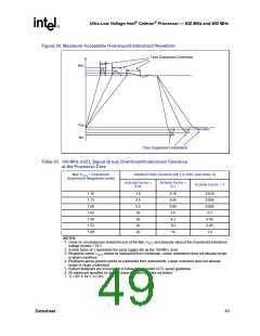
Overshoot and undershoot specifications are documented in Table 33 and illustrated in Figure 20.
48
Datasheet

 INTEL [ INTEL ]