Ultra-Low Voltage Intel® Celeron® Processor — 650 MHz and 400 MHz
4.3
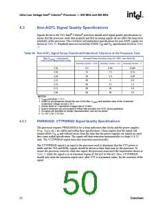
Non-AGTL Signal Quality Specifications
Signals driven to the ULV Intel® Celeron® processor should meet signal quality specifications to
ensure that the processor reads data properly and that incoming signals do not affect the long-term
reliability of the processor. The overshoot and undershoot specifications for non-AGTL signals are
shown in Table 34. Ringback must not exceed the CMOS VIH and VIL specification levels in Table
21.
Table 34. Non-AGTL Signal Group Overshoot/Undershoot Tolerance at the Processor Core
Max VCmos + Overshoot/
Allowed Pulse Duration (ns) [Tj=100C (see Note 6)]
Undershoot Magnitude (volts)
Activity Factor = 0.01 Activity Factor = 0.1 Activity Factor = 1
2.38
2.33
2.28
2.23
2.18
2.13
2.08
6.5
13
29
60
60
60
60
0.65
1.3
2.9
6
0.065
0.13
0.29
0.6
12
1.2
26
2.6
56
5.6
NOTES:
1. VCMOS(nominal) = 1.5 V.
2. Under no circumstances should the sum of the Max VCMOS and absolute value of the Overshoot/
Undershoot voltage exceed 2.38 V.
3. Activity factor of 1 represents a toggle rate of 33 MHz.
4. System designers are encouraged to follow Intel provided non-AGTL layout guidelines.
5. All values are specified by design characterization, and are not tested.
6. Tj = 85° C for 1.33 GHz.
4.3.1
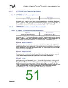
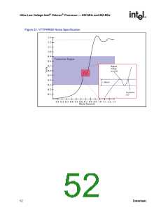
PWRGOOD, VTTPWRGD Signal Quality Specifications
The processor requires PWRGOOD to be a clean indication that clocks and the power supplies
(VCC, VCCT, etc.) are stable and within their specifications. Clean implies that the signal will
remain below V
and without errors from the time that the power supplies are turned on, until
IL18
they come within specification. The signal will then transition monotonically to a high (1.8 V)
state. The VTTPWRGD signal must also transition monotonically.
The VTTPWRGD signal is an input to the processor used to determine that the VTT power is
stable and the VID and BSEL signals should be driven to their final state by the processor. To
ensure the processor correctly reads this signal, the processor must meet the requirement shown in
Table 35 while the signal is in its transition region of 300 mV to 900 mV. Also, VTTPWRGD
should only enter the transition region once, after VTT is at nominal values, for the assertion of the
signal.
50
Datasheet

 INTEL [ INTEL ]