Ultra-Low Voltage Intel® Celeron® Processor — 650 MHz and 400 MHz
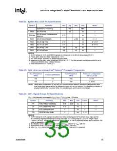
Table 22. System Bus Clock AC Specifications
Symbol
Parameter
Min
Typ
Max
Unit
Notes1
System Bus Frequency
BCLK Period
100
10
MHz
ns
T1S1
2
2
BCLK Period – Instantaneous
Minimum
T1S1abs
9.75
ns
T2S1
T3S1
BCLK Period Stability
BCLK High Time
BCLK Low Time
BCLK Rise Time
BCLK Fall Time
± 250
ps
ns
ns
ns
ns
2, 3, 4
at >2.0 V
at <0.5 V
5
2.70
2.45
0.4
T4S1
T5S1
1.6
1.6
T6S1
0.4
5
NOTES:
1. All AC timings for AGTL and CMOS signals are referenced to the BCLK rising edge at 1.25 V.
2. Period, jitter, skew and offset measured at 1.25 V.
3. Not 100% tested. Specified by design/characterization.
4. Measured on the rising edge of adjacent BCLKs at 1.25 V. The jitter present must be accounted for as a
component of BCLK skew between devices.
5. Measured between 0.5 V and 2.0 V.
Table 23. Valid Ultra-Low Voltage Intel® Celeron® Processor Frequencies
BCLK Frequency
(MHz)
Core Frequency
(MHz)
Power-on Configuration
bits [27,25:22]
Frequency Multiplier
100
100
6.5
4
650
400
0, 1111
0, 0010
NOTE: While other combinations of bus and core frequencies are defined, operation at frequencies other
than those listed above will not be validated by Intel and are not ensured. The frequency multiplier is
programmed into the processor when it is manufactured, and it cannot be changed.
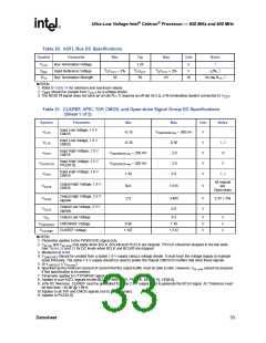
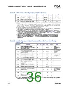
Table 24. AGTL Signal Groups AC Specifications
RTT = 56Ω internally terminated to VCCT; VREF = 2/3VCCT; load = 50 ohms
Symbol
Parameter
Min
Max
Unit
Figure
Notes1
T7
T8
AGTL Output Valid Delay
AGTL Input Setup Time
AGTL Input Hold Time
RESET# Pulse Width
0.40
1.30
1
3.25
ns
ns
ns
ms
7
8
2, 3
4
T9
8
T10
1
9, 10
NOTES:
1. All AC timings for AGTL signals are referenced to the crossing point of the BCLK rising edge and the
BCLK# falling edge for Differential Clocking and to the BCLK rising edge at 1.25 V for Single Ended
Clocking. All AGTL signals are referenced at VREF. RESET# may be asserted (active) asynchronously, but
must be deasserted synchronously.
2. Specification is for a minimum 0.40-V swing from VREF-200 mV to VREF+200 mV.
3. Specification is for a maximum 0.8-V swing from Vcct-0.8 V to Vcct.
4. After VCC, VCCT, and BCLK, BCLK# become stable and PWRGOOD is asserted.
Datasheet
35

 INTEL [ INTEL ]