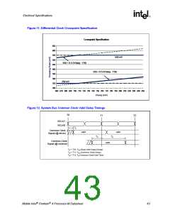
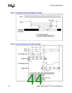
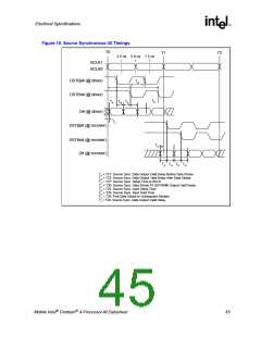
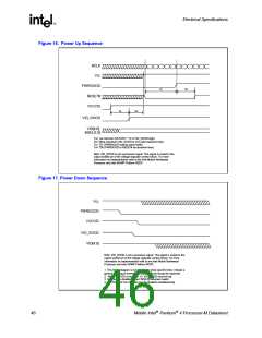
Electrical Specifications
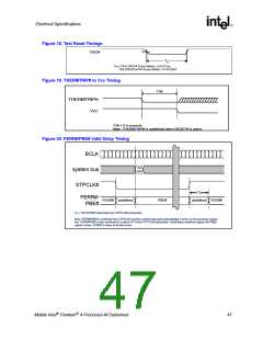
Figure 18. Test Reset Timings
1.25V
TRST#
T
q
Tq = T64 (TRST# Pulse Width), V=0.5*Vcc
= T37 (TRST# Pulse Width)
T
q
T38 (PROCHOT# Pulse Width), V=GTLREF
PCB-773
Figure 19. THERMTRIP# to Vcc Timing
T39
THERMTRIP#
Vcc
T39 < 0.5 seconds
Note: THERMTRIP# is undefined when RESET# is active
Figure 20. FERR#/PBE# Valid Delay Timing
BCLK
system bus
STPCLK#
SG
Ack
Ta
undefined FERR#
FERR#/
PBE#
FERR# undefined
PBE#
Ta = T40 (FERR# Valid Delay from STPCLK# Deassertion)
Note: FERR#/PBE# is undefined from STPCLK# assertion until the stop grant acknowledge is driven on the processor system
bus. FERR#/PBE# is also undefined for a period of Ta from STPCLK# deassertion. Inside these undefined regions the PBE#
signal is driven. FERR# is driven at all other times.
Mobile Intel Pentium 4 Processor-M Datasheet
47

 INTEL [ INTEL ]