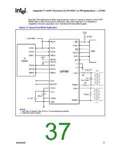
LXT362 — Integrated T1 LH/SH Transceiver for DS1/DSX-1 or PRI Applications
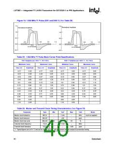
Figure 14. 1.544 MHz T1 Pulse (DS1 and DSX-1) (See Table 25)
1.5
1.0
0.5
0.0
-0.5
1.5
Normalized Amplitude
Normalized Amplitude
1.0
0.5
0.5
1.0
1.5
-0.5
0.5
1.0
1.5
-0.5
0.0
Time
(in Unit Intervals)
Time
(in Unit Intervals)
-0.5
Table 25. 1.544 MHz T1 Pulse Mask Corner Point Specifications
DS1 Template (per ANSI T1. 403-1995)
Minimum Curve Maximum Curve
DSX-1 Template (per ANSI T1. 102-1993)
Minimum Curve Maximum Curve
Time (UI) Amplitude
Time (UI)
Amplitude
Time (UI)
Amplitude
Time (UI)
Amplitude
-0.77
-0.23
-0.23
-0.15
0.0
-0.05
-0.05
0.50
0.90
0.95
0.90
0.50
-0.45
-0.45
-0.26
-0.05
-0.05
-0.77
-0.39
-0.27
-0.27
-0.12
0.0
0.05
0.05
0.80
1.20
1.20
1.05
1.05
-0.05
0.05
0.05
-0.77
-0.23
-0.23
-0.15
0.0
-0.05
-0.05
0.50
-0.77
-0.39
-0.27
-0.27
-0.12
0.0
0.05
0.05
0.80
1.15
1.15
1.05
1.05
-0.07
0.05
0.05
0.95
0.95
0.15
0.23
0.23
0.46
0.61
0.93
1.16
0.15
0.23
0.23
0.46
0.66
0.93
1.16
0.90
0.27
0.34
0.77
1.16
0.50
0.27
0.35
0.93
1.16
-0.45
-0.45
-0.20
-0.05
-0.05
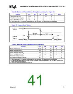
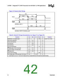
Table 26. Master and Transmit Clock Timing Characteristics (See Figure 15)
Parameter
Sym
Min
Typ1
Max
Unit
Notes
must be supplied
Master clock frequency
Master clock tolerance
Master clock duty cycle
Transmit clock frequency
Transmit clock tolerance
MCLK
MCLKt
MCLKd
TCLK
–
–
1.544
±50
–
–
–
MHz
ppm
%
40
–
60
–
1.544
–
MHz
ppm
TCLKt
–
±100
1. Typical figures are at 25 °C and are for design aid only; not guaranteed and not subject to production testing.
40
Datasheet

 INTEL [ INTEL ]