21150
Table 6. Secondary PCI Bus Interface Signals (Sheet 2 of 2)
Secondary PCI central function enable. When tied low,
s_cfn_l enables the 21150 secondary bus arbiter. When tied
high, s_cfn_l disables the internal arbiter. An external
secondary bus arbiter must then be used. Signal s_req_l<0> is
reconfigured to be the 21150 secondary bus grant input, and
s_gnt_l<0> is reconfigured to be the 21150 secondary bus
request output, when an external arbiter is used. Secondary
bus parking is done when s_req_l<0> is asserted, the
secondary bus is idle, and the 21150 does not want to initiate a
transaction.
s_cfn_l
I
2.4
General-Purpose I/O Interface Signals
Table 7 describes the general-purpose I/O interface signals.
Table 7. General-Purpose I/O Interface Signals
Signal Name
Type
Description
General-purpose I/O data. These four general-purpose signals
are programmable as either input-only or bidirectional signals
by writing the gpio output enable control register in
configuration space. The value on these signals is reflected in
a gpio input data configuration register when read. Levels to
be driven on gpio pins configured as bidirectional are derived
from the value written in the gpio output data configuration
register.
gpio<3:0>
TS
During the first 23 clock cycles (46 cycles when s_clk operates
at 66 MHz) while p_rst_l is deasserted and s_rst_l is asserted,
the gpio signals are used to control an external shift register
that can shift in a serial clock disable mask into the msk_in
input. The gpio pins should not be driven by software during
these 23 clock cycles. The mask can then be read and
modified in the secondary clock control register in
configuration space.
2.5
Clock Signals
Table 8 describes the clock signals.
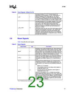
Table 8. Clock Signals (Sheet 1 of 2)
Signal Name
Type
Description
Primary interface PCI CLK. Provides timing for all transactions
on the primary PCI bus. All primary PCI inputs are sampled on
the rising edge of p_clk, and all primary PCI outputs are driven
from the rising edge of p_clk. Frequencies supported by the
21150 range from 0 MHz to 33 MHz, or 0 MHz to 66 MHz for a
66 MHz capable 21150.
p_clk
I
14
Preliminary Datasheet

 INTEL [ INTEL ]