IA186ES/IA188ES
Data Sheet
8-Bit/16-Bit Microcontrollers
November 15, 2011
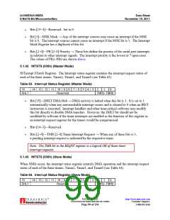
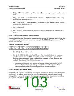
Bit [4]—TMR1 Timer1 Interrupt IN Service → Timer1 is being serviced when this bit is
set to 1.
Bit [3]—D1/I6 DMA Channel Interrupt 6 In Service → DMA channel 1 or int6 is being
serviced when this bit is set to 1.
Bit [2]—D0/I5 DMA Channel Interrupt 5 IN Service → DMA channel 0 or int5 is being
serviced when this bit is set to 1.
Bit [1]—Reserved.
Bit [0]—TMR0 Timer Interrupt In Service → Timer0 is being serviced when this bit is
set to 1.
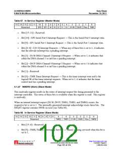
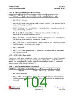
5.1.48 PRIMSK (02ah) (Master and Slave Mode)
PRIority MaSK Register. This register contains a value that sets the minimum priority level that
a maskable interrupt must have to generate an interrupt. The PRIMSK register contains 0007h
on reset (see Table 69).
Table 69. Priority Mask Register
15 14 13 12 11 10
9
0
8
0
7
0
6
0
5
0
4
0
3
0
2
1
0
0
0
0
0
0
0
PRM2–PRM0
Bits [15–3]—Reserved. Set to 0.
Bits [2–0]—PRM [2–0] Priority Field Mask → This three-bit field sets the minimum
priority necessary for a maskable interrupt to generate an interrupt. Any maskable
interrupt with a numerically higher value than that contained by these three bits, are
masked. The values of PR2–PR0 are shown above.
– Any unmasked interrupt may generate an interrupt if the priority level is set to 7.
However, by way of example, if the priority level is set to 4, only unmasked
interrupts with a priority of 0 to 5 are permitted to generate interrupts.
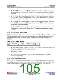
5.1.49 IMASK (028h) (Master Mode)
Interrupt MASK Register. The interrupt mask register is read/write. Setting a bit in this register
is effectively the same as setting the MSK bit in the corresponding interrupt control register.
Setting a bit to 1 masks the interrupt. The interrupt request is enabled when the corresponding
bit is set to 0. The IMASK register contains 07fdh on reset (see Table 70).
®
IA211050902-19
UNCONTROLLED WHEN PRINTED OR COPIED
http://www.innovasic.com
Customer Support:
Page 103 of 154
1-888-824-4184

 INNOVASIC [ INNOVASIC, INC ]